
Vision-based robotic system stacks tile slabs - Machine Vision Technology
Glass, Metal, Paper, Foil & Printing | Matching | Measuring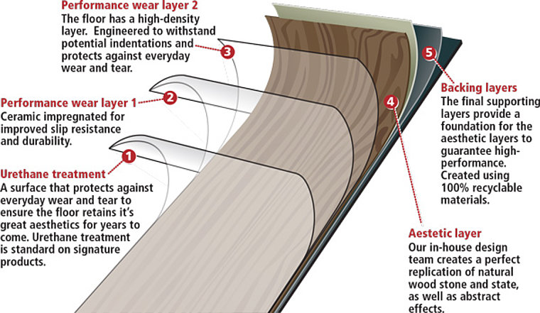
Unloading and stacking floor tile slabs onto a wooden pallet has been automated using a vision-guided robot.
Luxury vinyl tile flooring is an artificial flooring product which can be manufactured in a variety of designs, patterns, and textures to simulate real wood or stone. Amtico International (Coventry, UK, www.amtico.com), a designer and manufacturer of such products creates this flooring by bonding together a number of layers of film in a lamination process to produce a composite material whose layers each perform a unique function (Figure 1). The layers of film are manufactured on large rolls which are mounted onto a calender where the individual layers come together, are heated and then drawn between sets of pressurized rollers that laminate the layers into the composite product. At this point-while still hot-the embossed pattern is applied to complete a wood grain or other pattern. The material-which is in one long continuous sheet-is then cut into slabs by a guillotine. While the newly formed laminate slabs are still hot, a clear anti-scratch, anti-slip top coating is applied, after which the material is annealed (using intense heat followed by cooling) to reduce internal stresses to ensure that the finished product does not warp. The slabs now pass along a roller conveyor and continue cooling as they reach the unload station. Individual slabs are large (typically 1m x 1.2m), heavy and are produced approximately every 7s and unloading and stacking of the slabs onto a wooden pallet was a role originally performed by an operator. When a production run was changed from one style or size of tiling to another, the operator would ensure that the two styles or sizes of slabs were divided into separate pallets. To automate this process, Amtico International collaborated with Machine Vision Technology (Royal Leamington Spa, UK; www.machine-vision-technology.co.uk) to create a vision-based robotic system to relieve the operator of performing such arduous, repetitive and physically-demanding tasks. Seperated by vision In operation, the automated vision system captures an image of each slab and analyzes the image to determine its size, color and shade. It then compares this with the values from the previous slab. By doing so, the system can determine if a product change has taken place on the production line. After the vision inspection has taken place, slabs are transferred to a second conveyor. At this point, an ABB (Milton Keynes, UK; https://new.abb.com/uk) robot, installed by RM Group (Newtown, Powys, UK; www.rmgroupuk.com), picks the slabs from the conveyor and stacks them onto pallets. Once the vision system detects a product change, it instructs the robot to automatically switch the stacking to a new pallet. As the slab enters the vision station, a photoelectric retro-reflective sensor mounted beneath the conveyor detects the presence of the slab and a trigger is sent to the ABB robotic controller to inform the controller of the presence of the product. The robot controller then instructs a PC to trigger a Scout camera from Basler (Ahrensburg, Germany; www.baslerweb.com) fitted with a Computar (Cary, NC, USA; computar.com) lens to capture an image of the pallet which is then transferred to the PC over an Ethernet interface.
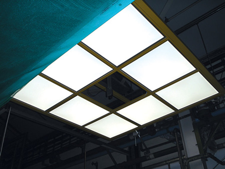
Machine Vision Technology's PC-based system runs a purpose designed application and user interface that shows the current slab, the last slab and also the live camera display. The vision analysis tools used were taken from the MVTec's HALCON library (Munich, Germany, www.mvtec.com) and supplied by MultiPix Imaging (Petersfield UK; www.multipix.com). Because of the nature of the application, it was impossible to fully enclose the vision system to ensure controlled lighting conditions. Instead, the camera was mounted in the center of an array of eight flat LED lighting panels each one being 600mm x 600mm located 3m above the conveyor. LEDs mounted in the rim of the panels emit light through a light guiding diffuser plate and exit the surface as uniform omni-directional diffused light, reproducing the effect of a coaxial or dome light (Figure 2). Although the vision station is out in the open on the factory floor, care was taken to ensure that it was not subject to direct sunlight. Changes in ambient lighting do not pose a problem because the system's color and shade measurements are always a relative comparison between the current slab and the last slab taken 7s previously.
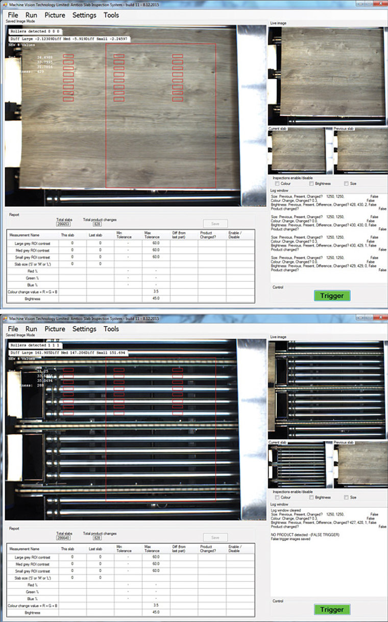
In addition, the light output from the dedicated lighting is high in comparison with the ambient lighting levels. Product change To determine whether a product change has occurred in the manufacturing process, the vision system makes three key measurements on the image of each slab captured by the camera. First, the system calculates the size of the slab to be palletized, a parameter which is determined by its length. Although a variety of traditional edge detection techniques could be employed, the edges of tile are difficult to determine since the underlying rollers of the conveyor may be detected as edges. Also, the print pattern may also contain many edges and the film layers of material at the edges of the slab may be staggered rather than uniformly formed on top of one another. To circumvent the issue, the system takes advantage of the highly reflective nature of the rollers on the conveyor. To determine whether the slab is small, medium or large, several rectangular regions of interest (ROIs) in the image of the slab are analyzed by the HALCON software. These ROIs were specified such that a large slab would obscure the light reflected from the rollers in all the regions of interest while medium or smaller-sized slabs would obscure light reflected from specific subsets. Hence by measuring the grey scale within each of the regions, the size of the slab can be determined from the list of known sizes, eliminating the need to measure the length directly. Due to the speed of the production process, it was important to eliminate the possibility of false triggering in the system due to spurious signals created by the sensor. These could be caused by a slab of material bouncing back from the end stop or a human operator placing his hand in front of the sensor. Because of the reflective surface of the rollers, the image can be analyzed to determine whether the rollers are covered or uncovered by the slab. Hence, the system is only positively triggered once a slab has covered a specific area under the rollers and is fully in the FOV of the camera (Figure 3). The second measurement made by the software determines the color of the slab. To do so, a section of several thousand pixels in the center of the tile are analyzed by the HALCON software. The relative percentage of red, green and blue are measured. By doing so, the color of the slab can be determined independently of the intensity. Although this is unimportant in the determination of the length of the product, modifying the tolerances of the color and the brightness parameters can accommodate any natural variation in the production process.
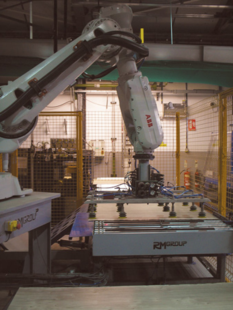
Because two slabs may be of the same color, but simply different shades of that color, it was also important to measure the brightness of the slab to detect the occasional product change that could potentially be missed by the other two measurements. To do so, the HALCON software measures the amplitudes of the red, green and blue content in a section of the image from which the brightness can then be calculated. A more detailed approach was considered based on the analysis of the hue, intensity and saturation of the slab image, but this was considered over-complicated and more difficult for the shop floor staff to visualize and hence more demanding for them to maintain the vision settings. The simplicity and flexibility of the system software enables the parameters used to analyze the images to be easily grasped and understood by the shop floor staff whose task it is to maintain the settings to ensure that the system is working optimally. Prior to picking the product, the slab is transferred from the conveyor to a second conveyor positioned at right angles to the first. The slab is then tracked by the system software until it reaches a further end stop where a photoelectric sensor detects its presence. The trigger signal from the second sensor is then used to instruct the ABB robot that the pallet is to be picked off the conveyor by its palletizing gripper fitted with nine vacuum cups and transferred to the pallet. If the system determines that consecutive images of the slab are the same, it instructs the robot to pick the tile from the conveyor and place it into the same pallet as the previous slab. If the system determines that a new size or style of product has been imaged, it instructs the robot to place the product into a new pallet (Figure 4). Cutting seams After the slabs of material have been palletized by the ABB robot, they are stored for a number of days prior to being guillotined a second time - this time across their transverse edge-into floorboard sized strips. The guillotine process ensures that the print layer is aligned with the edges of the complete slab and that the staggered layers of material at the very edges of the slab are removed.
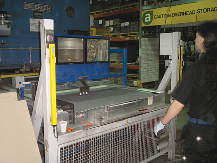
Currently, the operation is performed manually by an operator using a rudimentary system that comprises a camera and a simple live image display. By viewing the image of the slab on screen, an operator rotates the slab to orient it correctly under the guillotine (Figure 5). To automate this procedure, Machine Vision Technology has proposed using three Basler Scout color cameras which would capture images of three separate regions of the edge of the slab to determine the location of the edge of the print layer relative to the backing material to an accuracy of +/- 0.1mm. Having done so, the coordinates of the print layer could be fed to a robotic pick and place machine which would rotate the slab before feeding it into the guillotine. IR cameras look to detect uneven surfaces Having accomplished the goal of automating the palletization process, engineers at Amtico are now working with Machine Vision Technology to determine whether other areas of the tile production process might benefit from an automated vision-based system. More specifically, both companies are now developing a new vision system to detect any uneven surfaces produced in the slabs during the production process. The uneven surfaces are created in the slab after a roll changeover, when a fresh roll of film is overlapped and taped to the end of an old roll (a spliced joint). When this joint is laminated with other layers of film, the finished slab has a raised surface due to the presence of the overlapping joint. At the present time, such defective slabs are simply removed from the production process by an operator. Amtico had trialled a variety of 3D thickness measurement systems, but none proved reliable and robust enough to detect all the defects in a consistent fashion. This is because the thickness can vary by typically only 13 microns. This could conceivably be detected by a vision system under static lab conditions but when present on a bouncing fast moving web on the factory floor, the reliability of such a system would have been poor and the false defect rate high. Machine Vision Technology's proposed solution is to deploy an infrared (IR) camera to continually capture images of the moving web. The effectiveness of this idea relies on the fact that the material has just been laminated and is still hot. The taped seam (which could be in one of the underlying layers and so invisible on the surface) is thicker than the surrounding material and so is marginally hotter. To trial the approach, a Fluke (Everett, WA, USA; www.fluke.com/en-us) hand-held IR camera was used to image seams in the moving web. Having done so, the company is now considering deploying a 10fps 640 x 480 pixel industrial IR camera from FLIR (Wilsonville, OR, USA; www.flir.com) to capture images of the moving web at the full frame rate of the camera and analyze them in real time with HALCON. The presence of the seam would be detected as a bright (hot) band in the image. Its position on the web would then be recorded relative to the encoder count from the rollers on the conveyor. The PC would then automatically control a guillotine to cut the web just before and just after the seam. Once the seam is removed, the guillotine would return to its regular task of cutting the web into slabs. It is estimated that this system will have a payback period of a few days resulting in material savings.
Author: Brian Castelino Machine Vision Technology Ltd. (MVT) is a MVTec Certified Integration Partner.
Article kindly provided by Vision Systems Design. All product names, trademarks and images of the products/trademarks are copyright by their holders. All rights reserved.
