Closing the Ring – NP Plastics
Glass, Metal, Paper, Foil & Printing | Blob Analysis | Measuring
FireWire cameras, LED lighting, and software check for defects on plastic rings used to secure binders.
NP Plastics, a Dutch injection-molded plastics manufacturer, produces small plastic rings–among its many other products. These plastic rings are used in the closing mechanism of ring binders found in every office from Amsterdam to Hong Kong. To meet volume demand while improving quality, NP Plastics recently decided to install a machine-vision system to inspect the small plastic rings. The company turned to automation solution provider Radine with the support of Data Vision, Allied Vision Technologies' (AVT) sales partner in the Benelux. Data Vision developed a custom machine-vision solution using two AVT FireWire cameras, strobe and LED illumination, and MVTec Software GmbH's HALCON image-processing software running on a standard Dell PC to check the rings for burrs, undershots, and other spatial defects.
600 parts per minute
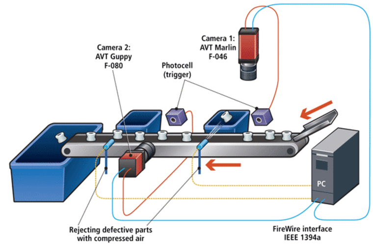
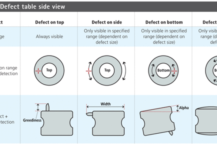
The plastic rings are fed into the inspection system by a PLC-controlled vibrating bowl feeder. The PLC and vision system communicate via digital I/O signals passed between the two machines that guarantee a supply of product is fed to the conveyor, and that the vision system is "active". The feeder orients the rings flat-side down and has a time-controlled gate that is configured to ensure that rings are spaced at a minimum interval of 40 mm on the inspection conveyor. At the maximum conveyor speed, this distance ensures that the machine-vision system will have 100 ms to acquire and process each image of each individual ring. Rings travel down the conveyor until they reach the first of two inspection stations. As the rings reach the side-view inspection station, a photocell mounted on the side of the conveyor triggers an AVT Guppy F-080 FireWire camera to acquire an image (see Fig. 1). "The smallest detail we need to detect is about 0.1 mm," explains Data Vision's machine vision engineer Robbert de Kraa. "Because we use a combination of blob analysis and measurement, we require four pixels minimum to robustly detect the smallest feature of 0.1 mm. With the field of view of 24 × 18 mm², a sensor is needed with a minimum resolution of 960 × 640 pixels. With a product rate of 10 products a second and some possible increase in the future, we selected an AVT Guppy F080B camera with a maximum frame rate of 30 frames/s and a resolution of 1032 × 778 pixels." FireWire was a good protocol selection, de Kraa explained, because of its high bandwidth and robustness against electromagnetic interference common to industrial environments. The side-view station looks for defects located around the edge of the plastic ring, including burrs on the top, bottom, and sides, as well as overshots that result in a rounded top or bottom rather than a flat ring.
In Table 1, the first row gives the type of defects, the second row specifies the range of the product where the defect is visible for the camera. The third row shows this range of the defect with arrows. The cross marks a defect. The fourth (bottom) row shows the defect in the camera view and the principle of detection in the image-processing algorithm. To minimize optical distortion at the edges of the camera's field of view while increasing contrast, de Kraa added a Jenoptik Jenmetar 0.2 × 12 telecentric lens and a TDB35 telecentric illumination lens fed by an optical fiber connected to a Volpi IntraLED 2020 white LED source to provide backlight illumination. The bright Volpi source allowed de Kraa to reduce the camera's shutter time to 200 µs, reducing the chance of blurring due to ring movement during exposure. The image from Station 1 is fed into the PC via an IOI Technology FireWire quadkaart. The MVTec HALCON software then takes over, using a combination of linear measurements and blob analysis to find burrs and other surface defects that exceed 0.1 mm. At the same time, a National Instruments PCI-6601 counter/timer card time-stamps the image, which represents the ring's location on the conveyor. Each inspection software application consists of two tasks. Task 1 takes care of the image acquisition and processing of the current product. The timestamp of each activity is then stored in a circular FIFO result buffer. This buffer contains result information for all the rings on the conveyor belt that have yet to pass the compressed-air rejection mechanism. Task 2 keeps track of the result buffer. It periodically (~ 1 ms) checks if there are still products in the buffer between camera and rejecter. If so, it takes the first pending unprocessed record and arms the hardware counter card with the time/counter stamp of the rejecter location, which is accurate to 10 ns. When the plastic ring reaches the rejecter location (e.g., when the hardware counter reaches the calculated exit location of this product), the timer/counter card fires the rejecter blower's solenoid. After the ring passes the rejecter position, this task finishes the current record and software increases the read pointer of the circular result FIFO. Since there is no physical connection between the application and conveyor belt by an encoder, the calculations are based on the speed setting of the conveyor belt. This approach simplifies the integration of the vision system with the material-handling system, making follow-up maintenance easier while reducing the bill of materials and system complexity.
Top-down approach
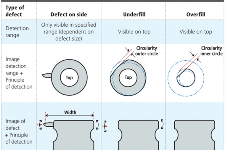
The plastic rings are also inspected by a vertically mounted camera. Minimum defect sizes for this station are 0.2 mm, allowing de Kraa to specify an AVT Marlin F033B camera with 656 × 494-pixel resolution with Pentax 50-mm entocentric machine-vision lens with 10-mm extension. For the top view, Data Vision designed a custom front illuminator using Luxeon (from Philips Lumileds Lighting Company) high-intensity red lumileds. The LEDs in a ring configuration are tilted inward slightly so that the top of the product as well as the borders are lit completely and evenly. The images are close to overexposure to cover the gray variation of the material and to get an even illumination in all cases. The LEDs are strobed to ensure a maximum of one pixel motion blur during exposure.
Again, the images are fed into the PC, and the HALCON software performs blob analysis and measurements to identify potential defects and classify the ring. Again, the National Instruments timing card tracks failed rings and triggers the air rejecter as necessary to separate bad parts from good (see Table 2).
The Radine/Data Vision system currently operates 24 hours a day. "We are especially proud of this sophisticated image-processing solution," says Bas H. Pot, who supervised the project at NP Plastics. "With this system, we can guarantee our most demanding clients that, even when millions of them are produced, each individual plastic roller that leaves our factory has had a complete check-up."
Author: Winn Hardin
Article kindly provided by Vision Systems Design.All product names, trademarks and images of the products/trademarks are copyright by their holders. All rights reserved.


