Fields for the Communication with the PLC
For each field in the .csv file, a specific memory block is reserved on the PLC. The fields are used by both the PLC and by the plug-in to write and read the required data. The fields can be separated into two blocks on the PLC's memory. One block of fields is used by the PLC to request commands or to define arguments for the execution. The other block is used by the plug-in to write information provided by the vision system, for example, general information on the vision system or the results of an execution. The PLC can read and process the information provided in the fields that are written by the plug-in and vice versa. Each field has a predefined name.
Some of the fields are a fixed part of the setup and will always be provided, for example, the field containing the current state of the vision system. We will refer to these type of fields as static fields. In contrast, there are also some dynamic fields which depend on the configuration of the plug-in and are provided only if the respective parameters of the plug-in are set accordingly, for example, the fields for result values. In the following sections, you can find an overview of the static fields which are a fixed part in the protocol and the dynamic fields which are added only if the plug-in is configured accordingly.
Exporting the Fields for the PLC
The set of fields can be exported in the "Communication" tab of the MERLIC RTE Setup.
- Select the desired MODICON®* plug-in instance on the left to show the configuration of the plug-in.
- If necessary, adjust the location and file name of the .csv file to be exported. The respective parameters are provided in the parameter category Export Symbols.
- Click on the "
 Start plug-in" button on the bottom of the MERLIC RTE Setup to export the fields to the specified .csv file.
The .csv file will be exported automatically as soon as the plug-in is started, that is, as soon as you click on the start button. It contains information on all required fields, the respective data type, and the assigned memory addresses. The file can be created independently of the PLC. A connection to the PLC is not required for the export. However, if the connection is not established yet, an error message occurs that the plug-in could not be started. You can ignore this error if you only wanted to export the .csv file.
When implementing the program for the PLC in "EcoStruxure™ Machine Expert - Basic", the exported file serves as reference for the fields and memory blocks that are required for the communication.
Importing the File with the Symbols
After exporting the selected fields of your plug-in configuration to a .csv file, you can import this file in "EcoStruxure™ Machine Expert - Basic" and use the respective fields for the implementation of the PLC program. You can import the file as described in the following steps.
- Go to the "Programming" window.
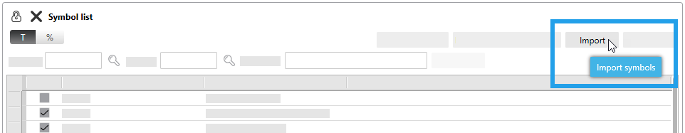
- Select the "Tools" tab on the left and click on "Symbol list".

- In the "Symbol list" window, click the "Import" button to open the dialog for the import.
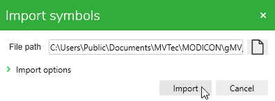
- Select the .csv file and click on "Import".
For our documentation, we use "EcoStruxure™ Machine Expert - Basic EcoStruxure™ Machine Expert - Basic is a PLC engineering software from Schneider Electric which can be used to configure, program, and monitor Modicon®* PLCs from Schneider Electric." version 1.2 SP1 Patch 1 build 65760. If you are using a different version of the program, the user interface and parameter names might differ from those shown in the example images. For information on "EcoStruxure™ Machine Expert - Basic", its features, and how to work with it to program and monitor Schneider Electric Modicon®* PLCs, please refer to the website of Schneider Electric.
Static Fields
This type of fields are always available for the communication. Most of them are written by the plug-in to provide information on the vision system or on the current execution. The PLC writes only a few of the static fields.
Static Fields Written by Plug-in
|
Field |
Data type |
Description |
|---|---|---|
|
GMV_VERSIONMAJOR |
INT |
Major version number of the plug-in. |
|
GMV_VERSIONMINOR |
INT |
Minor version number of the plug-in. |
|
GMV_CURRENTSTATE |
INT |
Current state of the MERLIC, for example, 72 for "SingleExecution". For more information on the values of the different state and how they are encoded, see the section MERLIC States. |
|
GMV_LASTRESULTID |
DINT |
ID of latest result. |
|
GMV_NUMBEROFRECIPES |
DINT |
Number of recipes that are available. |
|
GMV_PREPARERECIPEIDS |
ARRAY [0..31] OF BOOL |
Indicator which recipe is currently prepared. It contains an array in which each entry indicates whether the recipe corresponding to the index is currently prepared. This only works if 32 or fewer recipes are defined. In addition, only one recipe can be prepared when MERLIC is used. |
|
GMV_RUNNINGJOBID |
DINT |
ID of the job that is currently running. |
|
GMV_ACQUISITIONDONECOUNT |
DINT |
Number of image acquisitions that have been performed for the current job. Initially it is set to 0 which indicates that no images have been acquired yet. It is reset for each new job. |
|
GMV_ACKCOMMANDCODE |
INT |
Code of the requested command that has been acknowledged last by the plug-in. |
|
GMV_ERRORCODE |
DINT |
Numeric error code. It provides information on the nature of the error, the severity, and the affected component. For more information on how errors are returned, see the topic Error Handling. |
|
GMV_ERRORCAUSE |
INT |
Code of the command that caused an error. It assumes the same numeric value as given in the "GMV_REQCOMMANDCODE" and "GMV_ACKCOMMANDCODE" fields. For more information on how errors are returned, see the topic Error Handling. |
|
GMV_DROPPEDRESULTCOUNT |
DINT |
Number of results that have been dropped when using the result mode "Dequeue from buffer". Initially, it is set to 0 and incremented for each result that has been dropped. If the PLC does not dequeue the results fast enough and the result buffer capacity is exceeded, the oldest result in the buffer is dropped, that is, the result which would have been dequeued next. |
|
GMV_RESULTID |
DINT |
ID of the currently displayed result. |
|
GMV_RESULTRECIPEID |
DINT |
ID of the recipe which produced the displayed result. |
|
GMV_RESULTJOBID |
DINT |
ID of the which produced the displayed result. |
|
GMV_RESULTSTATE |
INT |
State of the displayed result:
|
Static Fields Written by PLC
|
Field |
Data type |
Description |
|---|---|---|
|
GMV_REQCOMMANDCODE |
INT |
Code of the requested command. For more information on the available commands and their codes, see the topic Communication between Plug-in and PLC . |
|
GMV_COMMANDRECIPEIDINUSE |
BOOL |
Indicator whether the recipe that is defined in "GMV_COMMANDRECIPEID" shall be used for the command requested in "GMV_REQCOMMANDCODE". |
|
GMV_COMMANDRECIPEID |
DINT |
ID of the recipe that will be used for the command requested in "GMV_REQCOMMANDCODE" if the value of "GMV_COMMANDRECIPEIDINUSE" is set to TRUE. |
Dynamic Fields
This type of fields are not provided by default. They are only added to the PLC memory if the plug-in is configured accordingly. Thus, the configuration of the plug-in determines which of the dynamic fields will be available for the communication. As with the static fields, some of the dynamic fields which are written by the plug-in and some others are written by the PLC. The following sections provide an overview of the dynamic fields.
Dynamic Fields Written by the Plug-in
|
Field |
Description |
|---|---|
|
GMV_RESULTUSEARRAY_<TYPE>_W0 |
Indicator whether any results of the respective data type are available to be queried. It contains an array in which each bit serves as indicator for a specific result of this data type. The size of the array depends on the configuration of the plug-in, that is, it depends on the setting for the respective result data type in the category Writing Data to PLC Memory. For example, if the plug-in parameter "INT (signed 16-bit integer) result allocation" is set to 2, the field "GMV_RESULTUSEARRAY_INT_W0" will be added to the PLC memory. If the two least significant bits of "GMV_RESULTUSEARRAY_INT_W0" are However, if the plug-in configuration defines more than 16 results for the data type INT, the bits in the "GMV_RESULTUSEARRAY_INT_W0" field are not enough to indicate the availability for each result. In this case, another field "GMV_RESULTUSEARRAY_INT_W1" will be added. This field can then be used as indicator for the next 16 results of data type INT. Available data types:
|
|
GMV_RESULT_<TYPE>_<INDEX> |
Actual result values of the data types BOOL, INT, DINT, and REAL. Each result is written to its own field. The symbol of a result field is composed of the prefix "GMV_RESULT_" followed by the data type and the index of the result. These type of fields will only be added to the PLC memory if the configuration of the plug-in is set accordingly in the category Writing Data to PLC Memory. For example, if the plug-in parameter "INT (signed 16-bit integer) result allocation" is set to 2, two fields for the result values will be added to the PLC memory: "GMV_RESULT_INT_0" and "GMV_RESULT_INT_1". |
|
GMV_RESULT_STRING80_<INDEX>_W<WORD_INDEX> |
Actual result values for of data type STRING[80]. For a result of data type STRING[80], 40 register addresses are reserved because it is mapped via a sequence of single WORDS. This means that there are 40 fields for the value of a single STRING[80] result. The symbols of these fields are composed similar to the ones for results of other data types but with an additional suffix: "W<WORD_INDEX>". The additional suffix is composed of the character "W" and an index number. This index number indicates to which of the 40 WORDS containing the STRING[80] value, that is, to which bytes, the respective field refers to. For example, the symbols of the fields that are reserved for the first result value of data type STRING[80] are the following: "GMV_RESULT_STRING80_0_W0", "GMV_RESULT_STRING80_0_W1", and so on until "GMV_RESULT_STRING80_0_W39". The first index 0 of all these symbols indicates that the fields refer to the first result value of type STRING[80]. The second index refers to the respective word within the sequence of singe WORDS. Thus, the field with symbol "GMV_RESULT_STRING80_0_W0" is used for the first two bytes of the first STRING[80] result. The field with symbol "GMV_RESULT_STRING80_0_W1" is used for the third and fourth byte of the first STRING[80] result and so on until the field with symbol "GMV_RESULT_STRING80_0_W39" which is used for the last two bytes. These type of fields will only be added to the PLC memory if the configuration of the plug-in is set accordingly in the category Reading Data from PLC Memory. For example, if the plug-in parameter "STRING[80] result allocation" is set to 2, 80 fields for the result values will be added to the PLC memory: 40 fields for the value of the first STRING[80] result ("GMV_RESULT_STRING80_0_W0" to "GMV_RESULT_STRING80_0_W39") and 40 fields for the value of the second STRING[80] result ("GMV_RESULT_STRING80_1_W0" to "GMV_RESULT_STRING80_1_W39"). |
Dynamic Fields Written by the PLC
|
Field |
Description |
|---|---|
|
GMV_ITPARAMUSEARRAY_<TYPE>_W0 |
Indicator whether the recipe parameters of the respective data type shall be overwritten for the next execution by the values defined in the fields of the corresponding iteration parameters. It contains an array in which each bit serves as indicator for a specific iteration parameter of this data type. The size of the array depends on the configuration of the plug-in, that is, it depends on the setting for the respective iteration parameter data type in the category Reading Data from PLC Memory. For example, if the plug-in parameter "INT (signed 16-bit integer) iteration parameter allocation" is set to 2, the field "GMV_ITPARAMUSEARRAY_INT_W0" will be added together with the fields "GMV_ITPARAM_INT_0" and GMV_ITPARAM_INT_1" for the values of the iteration parameters. If the first two bits of "GMV_ITPARAMUSEARRAY_INT_W0" are set to However, if the plug-in configuration defines more than 16 iteration parameter for the data type INT, the bits in the "GMV_ITPARAMUSEARRAY_INT_W0" are not enough to indicate for each iteration parameter if the respective value should be used for the next execution. In this case, another field "GMV_ITPARAMUSEARRAY_INT_W1" will be added. This can then be used for as indicator for the next 16 iteration parameter of data type INT. |
|
GMV_ITPARAM_<TYPE>_<INDEX> |
Values for iteration parameters of the data types BOOL, INT, DINT, and REAL. The symbol of the respective fields is composed of the prefix "GMV_ITPARAM_" followed by the data type and the index of the iteration parameter. These type of fields will only be added to the PLC memory if the configuration of the plug-in is set accordingly in the category Reading Data from PLC Memory. For example, if the plug-in parameter "INT (signed 16-bit integer) iteration parameter allocation" is set to 2, two fields for the result values will be added to the PLC memory: "GMV_ITPARAM_INT_0" and "GMV_ITPARAM_INT_1". |
|
GMV_ITPARAM_<TYPE>_<INDEX>_W<WORD_INDEX> |
Values for iteration parameters of data type STRING[80]. For an iteration parameter of data type STRING[80], 40 register addresses are reserved because it is mapped via a sequence of single WORDS. This means that there are 40 fields for the value of a single STRING[80] parameter. The symbols of these fields are composed similar to the ones for iteration parameters of other data types but with an additional suffix: "W<WORD_INDEX>". The additional suffix is composed of the character "W" and an index number. This index number indicates to which of the 40 WORDS, that is, to which bytes, the respective field refers to. For example, the symbols of the fields that are reserved for the first iteration parameter of data type STRING[80] are the following: "GMV_ITPARAM_STRING80_0_W0", "GMV_ITPARAM_STRING80_0_W1", and so on until "GMV_ITPARAM_STRING80_0_W39". The first index 0 of all these symbols indicates that the fields refer to the first iteration parameter of type STRING[80]. The second index refers to the respective word within the sequence of singe WORDS. Thus, the field with symbol "GMV_ITPARAM_STRING80_0_W0" is used for the first two bytes of the first STRING[80] parameter value. The field with symbol "GMV_ITPARAM_STRING80_0_W1" is used for the third and fourth byte of the first STRING[80] parameter and so on until the field with symbol "GMV_ITPARAM_STRING80_0_W39" which is used for the last two bytes. These type of fields will only be added to the PLC memory if the configuration of the plug-in is set accordingly in the category Reading Data from PLC Memory. For example, if the plug-in parameter "STRING[80] iteration parameter allocation" is set to 2, 80 fields for the result values will be added to the PLC memory: 40 fields for the value of the first STRING[80] parameter ("GMV_ITPARAM_STRING80_0_W0" to "GMV_ITPARAM_STRING80_0_W39") and 40 fields for the value of the second STRING[80] parameter ("GMV_ITPARAM_STRING80_1_W0" to "GMV_ITPARAM_STRING80_1_W39"). When requesting a "StartSingleJob" or "StartContinuous" command, the first two bits of "GMV_ITPARAMUSEARRAY_STRING80_W0" will indicate whether these values will be used to override the respective values defined in the recipe. |
MERLIC States
When using the MODICON®* plug-in, the internal state of MERLIC is transmitted to the PLC via the field "GMV_CURRENTSTATE".
The byte that transmits the information about the current state is encoded as follows:
|
Bit field position |
Numeric value |
MERLIC state |
Description |
|---|---|---|---|
|
0 |
1 |
Preoperational |
If this bit is set to 1, MERLIC is in the state "Preoperational". |
|
|
|
OperationalAutomaticMode Initialized Ready SingleExecution ContinuousExecution |
If this bit is set to 1, MERLIC is in the state "OperationalAutomaticMode". This means that MERLIC is either in the state "Initialized", "Ready", "SingleExecution", or "StartContinuous":
|
|
|
|
Halted |
If this bit is set to 1, MERLIC is in the state "Halted". |
|
|
|
Error |
If this bit is set to 1, MERLIC is in the state "Error". |
|
|
|
OperationalFrontendAccessMode |
If the 3rd and 8th bit are set, MERLIC is in the manual mode. This means that MERLIC can be controlled only via the MERLIC Frontend. For more information about the manual mode, see the topic Write Access in the Frontend in the MERLIC manual. |
For more information about the available states of MERLIC and its transitions, see the topic MERLIC States in the MERLIC manual.
* Modicon® is a registered trademark of Schneider Electric USA, Inc.

