Configuring a Camera Device with I/O Channels
The process integration MERLIC can be used in machine vision systems that are integrated in a manufacturing machine. The machine controller, e.g., a programmable logic controller (PLC), must be able to control an integrated vision system, to monitor the execution, and to query the results. Therefore, MERLIC provides a process integration mode to enable the communication with a machine controller.
The process integration mode can be started with the application "MERLIC RTE" that is provided with the MERLIC installation. mode of MERLIC enables you to control the execution of MERLIC via a camera device with GenICam compliant digital I/O channels. To establish a communication with such a camera device, you first have to select the respective device in the "![]() I/O" tab of the MERLIC RTE Setup and configure the device for the process integration. If you have selected a device, you can get information about which signals are transmitted via the respective input channels. In addition, you can start to configure the channels for the digital outputs.
I/O" tab of the MERLIC RTE Setup and configure the device for the process integration. If you have selected a device, you can get information about which signals are transmitted via the respective input channels. In addition, you can start to configure the channels for the digital outputs.
To check or modify the current configuration of the digital inputs and outputs of a device, you have to activate the device first via "Enable device".
Requirements
To use the process integration mode with a camera device with digital I/O channels, the following requirements are necessary:
- Ensure that the camera device provides at least 1 input channel and at least 2 output channels. For the transmission of results, 1 further output channel is required so there are 3 output channels in total.
- Ensure that the driver for the I/O interface is installed on the same PC as MERLIC.
- Ensure that the respective MVTec I/O interface is of version 20.11.16 (or higher) and stored in the bin directory of the MERLIC installation. You can download the MVTec I/O interface from the MVTec website.
Standard Features Naming Convention (SFNC)
For the I/O configuration to work, the digital I/O control parameters of your camera device need to match the names and values specified by the Standard Features Naming Convention (SFNC). If this is not the case, MERLIC will not recognize the I/O channels and the I/O device will not appear in the list of connected devices on the "I/O" tab of the MERLIC RTE Setup.
You can make sure that your camera device comes with the proper specifications by connecting the camera device to the Image Source Manager (ISM). By consulting the list of camera parameters that is visible in the ISM, you can check if the names and values of the camera parameters match the specifications of the SNFC.
These are the digital I/O control parameters that are required by MERLIC:
- LineX (Line1, Line2, etc.)
- LineFormat
- LineInverter
- LineMode
- LineSelector
- LineSource
- LineStatusAll
- UserOutputSelector
- UserOutputValue
If the digital I/O control parameters of your camera device do not match the specifications of the SNFC, please contact the MVTec Help Desk.
Restrictions
If you want to provide multiple recipe files for the process integration, you have to make sure that all referenced MERLIC Vision Apps acquire the images via the Image Source Manager (ISM) instead of the deprecated "Acquire Image from Camera" tool. Otherwise, MERLIC cannot be started in process integration mode.
However, the camera device can only be accessed by one MERLIC instance at a time. If another MERLIC instance is already accessing the camera device when you start the I/O configuration, the camera device will not be visible in the list of available devices in the "I/O" tab of the MERLIC RTE Setup. This might happen, if you are accessing the camera device via MERLIC Creator, for example, by acquiring images in an MVApp via ISM or the deprecated MERLIC tool "Acquire Image from Camera".
If your camera device is not visible in the "I/O" tab after refreshing the list of available devices, there are several things you can do:
- If your MVApp acquires images via ISM, you have to ensure that the image source configuration of your camera device is not activated in the "Image Source" tab, i.e. that its configuration status is set to "inactive".
- If your MVApp acquires images via the deprecated MERLIC tool "Acquire Image from Camera", you have to ensure that the connection to your camera device is not activated in your MVApp, i.e., that the tool parameter "Connect" is set to 0.
- To avoid this issue altogether, start by closing all instances of MERLIC. You can then start the MERLIC RTE Setup via the Windows start menu or the command line to make sure that the MERLIC Creator is not running and thus not accessing your camera device.
If the camera device you are trying to configure does not appear in the list of available devices on the "I/O" tab of the MERLIC RTE Setup, make sure that it is not already actively connected to the Image Source Manager or a deprecated "Acquire Image from Camera" tools.
Selecting the Acquisition Interface
- Select the camera device as described in Selecting Devices for the Process Integration.
- Select the respective acquisition interface of the camera device in the "General" section of the configuration area. If you are not sure which interface you need to select, you can look up the name of the interface in the Image Source Manager.
- Go to the "Image Sources" tab in the MERLIC RTE Setup, select the image source configuration in which the camera device is configured, and look up the name of the interface in the overview of the image sources.
- Go back to the "I/O" tab, scroll down to the section "General", and select the acquisition interface from the drop-down menu.
Configuring the Digital Inputs
MERLIC assigns the input signals to the available device channels automatically according to the default configuration. The configuration area in the "I/O" tab displays the current pairs of MERLIC signals and digital I/O channels. The digital input channels are listed in the section "Input". You can change the default configuration of the channels manually in the configuration area.
For camera devices with digital I/O channels, the following signal is available:
|
Signal |
Description |
|---|---|
|
StartSingleJob |
Triggers a single execution of the MERLIC Vision App. |
See the topic Signals and Commands for Digital I/O Devices for more information about the available signals and commands.
How to Assign the Digital Input Channel
To configure the digital input channel, you can proceed as follows:
- Select the camera device from the list of devices as described in section Selecting the Camera Device.
- Click on the channel drop-down menu of the "StartSingleJob" signal and select a different channel from the list.
- Save the configuration via the "
 Save" button. Your configuration is saved as long as the device is enabled. If you disable the device, i.e., remove it from the list of enabled devices, the respective changes will be lost and the default configuration is restored.
In the example configuration below, the signal for "StartSingleJob" is transmitted via the input channel di_0.0.

Configuring the Digital Outputs
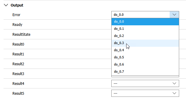
MERLIC assigns the output signals to the available device channels automatically according to the default configuration. The configuration area in the "I/O" tab displays the current pairs of MERLIC signals and digital I/O channels. The list of available signals and digital output channels is shown in the section "Output". If desired, you can change the default configuration of the channels manually in the configuration area.
For camera devices with digital I/O channels, the following signals are available for the transmission:
|
Signal |
Description |
|---|---|
|
Error |
Indicates if an error occurred. |
|
Ready |
Indicates if MERLIC is ready for execution. |
|
ResultState |
Indicates the state of the state of the queried result data. If it is set to 1, the processing was carried out correctly and the queried results are up-to-date. If it is set to 0, the processing failed or was aborted. In this case, no results might be available or the existing result values might not be up-to-date, e.g., the values might be outdated and from a previous execution.
|
|
Resultn |
Represents the n-th MVApp result that has been defined for the MVApp that is referenced in the recipe file. |
See the topic Signals and Commands for more information about the MERLIC states and signals.
How to Assign the Digital Output Channels
To configure the digital output channels, proceed as follows:
- Select the camera device from the list of devices as described in section Selecting the Camera Device.
- For each signal whose configuration you want to modify, perform the following step:
- Click on the drop-down menu of the signal and select a different channel from the list.
- Click on the drop-down menu of the signal and select a different channel from the list.
- Save the configuration via the " Save" button. Your configuration is saved as long as the device is enabled. If you disable the device, i.e., remove it from the list of enabled devices, the respective changes will be lost and the default configuration is restored.
This way, you can modify the configuration which output channel transmits a specific signal. Since it is optional to assign an output channel to a result, it is possible to select the entry "--" instead of a channel.
As an alternative way to display a list of available devices for the process integration mode with their default configuration you can start MERLIC with the command line option "--devices" from the directory where MERLIC is installed.
It is mandatory to select a channel for the signals "Error" and "Ready" because they contain the decisive information about the current MERLIC state. In addition, channels cannot be assigned more than once.
Resetting the Changes
To restore the default configuration for your device, reset the changes for the digital inputs, digital outputs, and the acquisition interface by clicking on "![]() Reset to default" at the respective section.
Reset to default" at the respective section.
Disabling the Device
To disable a device for the configuration use the "![]() Disable device" button. The device will be moved to the list of available devices and the configuration of the device will be deleted.
Disable device" button. The device will be moved to the list of available devices and the configuration of the device will be deleted.

