Deflectometry is useful for inspecting reflective (specular) surfaces. These surfaces are tricky to inspect with other methods, due to a mirror image appearing on the surface. Chapter 8 in the HALCON Solution Guide I describes the principle of deflectometry, which uses the specular reflections by observing mirror images of known grey code patterns and their deformations on the surface.
As usual, speed is an important factor. In deflectometry, speed is not necessarily limited by the algorithms; instead, the limitation mainly comes from hardware constraints and synchronization. When acquiring a single structured light pattern with the camera, we have to know which pattern is acquired. Thus, previously displayed stripes should not be visible. Below, we will introduce three ideas how to deal with this synchronization problem. These differ in terms of implementation complexity and speed-up potential.
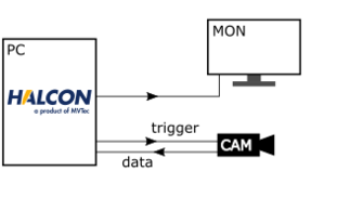
The simplest set-up (see Fig. 1) basically uses the operator structured_light_camera_screen_sync() to find a suitable delay for each image acquisition. This ”quick win” requires no additional hardware besides the monitor and camera and no special configuration. Naturally, the acquisition speed is limited well below the frame rates of both camera and monitor.
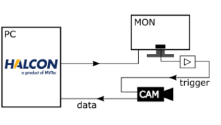
Improved synchronization can be achieved using hardware triggers (see Fig. 2). Using photo sensors in a small area of the monitor is described in solution guide I section 8.3.3. This “hardware-only” improvement directly triggers the camera when the monitor image changes. Advantages include speed-up thanks to synchronization, a simple and robust set-up without significant additional hardware cost. Acquisition frame rates of around 12 to 16 frames per second (fps) are realistic.
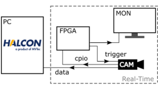
Finally, a potential set-up using dedicated FPGA Hardware can be seen in in Fig. 3. An FPGA evaluation board can be used to control both the monitor and camera synchronization. The pattern is generated directly in the FPGA using the VGA output, and the camera is triggered through one of the logical outputs. For as little as the costs of an development board (~ €150) synchronization using real-time programming can be realized. The acquisition frame rate achieved in a demonstration set-up was 30 fps. Adjustments to the phase-locked loops (PLL), hardware choices, or innovative set-up arrangements could push the acquisition frame rate beyond the capabilities of a standard 60-fps monitor.
Please note: These results are from test stands that do not claim to be suitable for industrial use.


