Configuring the Plug-in
The configuration of the MODICON®* plug-in can be adjusted in the "Communication" tab of the MERLIC RTE Setup. In the "Communication" tab, you can add an instance of the MODICON®* plug-in, configure the parameters, and you can start and stop the plug-in directly in the user interface.
Enabling the Configuration in the MERLIC RTE Setup
To enable the configuration of the plug-in in the "Communication" tab of the MERLIC RTE Setup, you first have to start the MERLIC Communicator and perform the following steps:
- Open the MERLIC RTE Setup and go to the "Communication" tab. In case the MERLIC Communicator is not running, you can start it directly from the "Communication" tab.
-
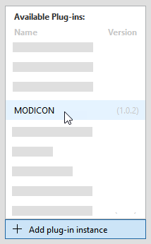
- Make sure that the plug-in is currently not running. Otherwise, the parameters are not available for the configuration. You can see the current state of the plug-in at the respective status icon in the list of plug-in instances. If the status shows the icon
 , the plug-in is running. In this case, you have to stop it by clicking the "
 Stop plug-in" button on the bottom of the MERLIC RTE Setup. If the status shows the icon
  instead, the plug-in is currently not running.
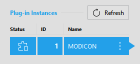
-
Plug-in Parameters
Parameters of this type represent general parameters for the Communicator plug-in that cannot be adjusted in the configuration area of the "Communication" tab. They may show the version number of the plug-in, the current parameter value for the log level, the access level of the plug-in, and the setting for the validation of the plug-in configuration. These values need to be set in different locations or with different methods, respectively.
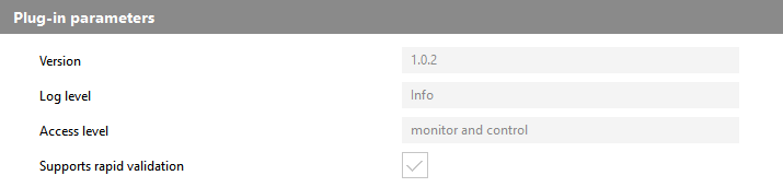
Version
This parameter shows the version number that has been defined during the plug-in implementation. It consists of a major, minor, and maintenance version. It is also shown when adding a new plug-in instance. The version is optional. Therefore, it is possible that no version number has been defined during the implementation.
Log level
You can also set a different log level for the Communicator in general or for a specific plug-in instance only. For more information, see the section Starting a Plug-in with a Specific Log Level in the topic Starting and Stopping Plug-ins of the MERLIC manual.
Access level
This parameter shows the access level that is set for the plug-in. For the MODICON®* plug-in, the access level is set to "monitor and control" by default. This means that the plug-in can receive "events" and send "actions". The access level correlates with the capability that is defined in the implementation of the plug-in. The implemented capability cannot be adjusted in the MERLIC RTE Setup.
Supports rapid validation
This parameter shows whether the plug-in supports the immediate validation of the current plug-in configuration. For this plug-in, the check box is ticked indicating that "rapid validation" is supported. This means that the configuration of the plug-in is validated with each modification of any editable parameter in the "Communication" tab of the MERLIC RTE Setup. If the plug-in does not support "rapid validation", the configuration of the plug-in is validated only when saving the configuration.
User Parameters
The "User parameters" represent the set of parameters that can be configured for the plug-in. They are displayed in different categories which can be expanded or closed.
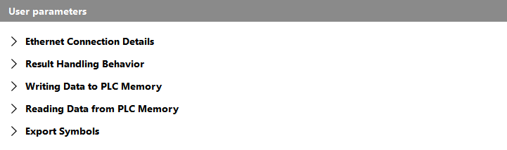
The following sections describe the parameters for each category.
- Ethernet Connection Details
- Result Handling Behavior
- Writing Data to PLC Memory
- Reading Data from PLC Memory
- Export Symbols
Ethernet Connection Details
The parameters in this category define the settings for the connection to the Schneider Electric Modicon®* PLC. For more information on how to set up the connection to the PLC, see the topic Setting Up the Connection to the PLC.
The following image shows an overview of the parameters with the respective default setting. A detailed description of the parameters follows after the image.

IP address
This parameter defines the Internet Protocol address (IP address) of the MODICON®* PLC to which you want to connect. By default, it is set to "127.0.0.1". The parameter supports only Internet Protocol version 4 (IPv4) addresses. The usage of host names is thereby not supported.
Port
This parameter defines the port used for the connection.
Result Handling Behavior
The parameters in this category define settings with respect to the retrieval of the results.
The following image shows an overview of the parameters with the respective default setting. A detailed description of the parameters follows after the image.
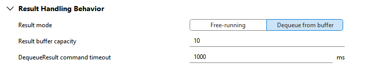
Result mode
This parameter allows you to select the mode of querying the results. You can choose between "Free-running" and "Dequeue from buffer". By default, the parameter is set to "Dequeue from buffer". In the following table, we give a short description for each mode.
|
Mode |
Description |
|---|---|
|
Free-running |
In this mode, the results of a single or continuous execution are immediately written to the respective memory addresses of the PLC without any handshake mechanism. This mode is the fastest but it can also be the most error prone. Depending on the timing of both MERLIC and the PLC, it might be possible that some results get lost or overwritten before the PLC can collect them. |
|
Dequeue from buffer |
In this mode, an internal FIFO queue is used to save the incoming results after starting a single or continuous execution. If the PLC requests a result by setting the "gMV_ReqCommandCode" to 10, the first result in the buffer is written to the respective memory address of the PLC. The requested result is then immediately removed from the queue. |
Result buffer capacity
This parameter defines the size of the buffer which is used to temporarily store the results when using "Dequeue from buffer" as result mode. It represents the number of results that can be saved in the buffer. By default, it is set to 10.
This parameter is used only if "Dequeue from buffer" is set as result mode. It has no effect if "Result mode" is set to "Free-running". Therefore, it will be deactivated for configuration if the "Free-running" mode is selected.
DequeueResult command timeout
This parameter defines the timeout for the "Dequeue from buffer" mode when waiting for a new result. If the PLC requests a result and the respective result is not available yet, all other requests will be blocked until the result is available or until the specified timeout expired. By default, the timeout is set to 1000 ms.
This parameter is used only if "Dequeue from buffer" is set as result mode. It has no effect if "Result mode" is set to "Free-running". Therefore, it will be deactivated for configuration if the "Free-running" mode is selected.
Writing Data to PLC Memory
The parameters in this category define how many results of each data type can be transmitted to the PLC.
For each result you want to transmit, you have to reserve a so-called field. A field represents a specific memory block on the PLC which is used for the respective result value. However, there are also fields for other contents or for commands, for example, for the current state or to request commands.
By default, no fields are reserved for any result data type. This means that no results will be transmitted to the PLC.
To enable the transmission of a result, you have to select the parameter that represents the respective data type of the result and set its value to the number of results you want to transmit. If you are not sure of the result's data type, you can look it up in the MVApp. For example, if your MVApps may contain up to five MVApp results of data type INT, you have to set the respective parameter in the plug-in's configuration, "INT (signed 16-bit integer) result allocation", to at least 5 to ensure that the values of all INT results will by available for the PLC.
If more results of a specific data type are transmitted than specified in the plug-in configuration, not all parameters will be available because not enough register addresses were reserved on the PLC.
If you set the parameter "INT (signed 16-bit integer) result allocation" to 2, the PLC will be able to query up to two results of data type INT.
- GMV_RESULTUSEARRAY_INT_W0
- GMV_RESULT_INT_0
- GMV_RESULT_INT_1
If only one INT result is transmitted, not all of the reserved registers on the PLC will be used. However, if more than two results of data type INT are transmitted, for example, because the MVApp of the prepared recipe contains more than two INT results, only the first two results will be available to be queried by the PLC because the plug-in reserved only the register addresses for two INT results.
The following image shows an overview of the parameters. A detailed description of the parameters follows after the image.
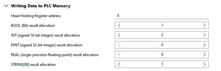
Head Holding Register address
This parameter defines the first "Holding Register Address" of the block that is reserved on the PLC. This block includes all values that are written by the plug-in and read by the PLC, for example, the current state and result values.
By default, it is set to 0 which corresponds to %MW0 on the PLC.
BOOL (Bit) result allocation
This parameter defines the number of Boolean results that can be transmitted to the PLC. For example, if you want to transmit up to five Boolean results, set the parameter to at least 5.
By default, the parameter is set to 0 which means that no Boolean result will be transmitted.
Parameters of this data type require exactly 1 bit. Therefore, exactly one bit of a register address is mapped to the field of a Boolean result provided that up to 16 results are selected. The individual results within a given register are addressed using a hexadecimal digit, for example, %MW35:X0. If more than 16 Boolean results are returned, further register addresses are mapped to provide a field for each result.
INT (signed 16-bit integer) result allocation
This parameter defines the number of INT results that can be transmitted to the PLC. For example, if you want to transmit up to five INT results, set the parameter to at least 5.
By default, the parameter is set to 0 which means that no INT result will be transmitted.
Parameters of this data type require exactly 16 bits which correspond to exactly one register address, for example, %MW36.
DINT (signed 32-bit integer) result allocation
This parameter defines the number of DINT results that can be transmitted to the PLC. For example, if you want to transmit up to five DINT results, set the parameter to at least 5.
By default, the parameter is set to 0 which means that no DINT result will be transmitted.
Parameters of this data type require exactly 32 bits which correspond to exactly two register addresses. Therefore, two registers are reserved but only the address of the first will be mapped, for example, %MD37 if the addresses %MD37 and %MD38 are used. The prefix "%MD" of the address also indicates that parameters of this data type are mapped via a double word.
REAL (single-precision floating-point) result allocation
This parameter defines the number of REAL results that can be transmitted to the PLC. For example, if you want to transmit up to five REAL results, set the parameter to at least 5.
By default, the parameter is set to 0 which means that no REAL result will be transmitted.
Parameters of this data type require exactly 32 bits which correspond to exactly two register addresses. Therefore, two registers are reserved but only the address of the first will be mapped, for example, %MF39 if the addresses %MF39 and %MF40 are used. The prefix "%MF" of the address also indicates that parameters of this data type are mapped via a double float word.
STRING[80] result allocation
This parameter defines the number of STRING[80] results that can be transmitted to the PLC. For example, if you want to transmit up to five STRING[80] results, set the parameter to at least 5. The PLC will reserve and map the register addresses for the required fields.
By default, the parameter is set to 0 which means that no STRING[80] result will be transmitted.
Parameters of this data type require exactly 80 bytes (640 bits) which corresponds to exactly 40 register addresses. They are mapped via a sequence of single WORDS, for example, %MW41 to %MW80, each corresponding to two bytes of ASCI characters. The symbols of the fields will be composed of several components. The first component is the prefix "GMV_RESULT_STRING80" which indicates that the field refers to a result of data type STRING[80]. The second component is the index of the respective MVApp result. The third and last component is a suffix which is composed of the character "W" and an index number which indicates to which of the 40 registers containing the STRING[80] value the respective field refers to.
For example, the field with symbol "GMV_RESULT_STRING80_0_W0" references the first register address which is reserved for the first STRING[80] result. Thus, it will be used for the value of the first two bytes of the first STRING[80] result. The fields "GMV_RESULT_STRING80_0_W0" to "GMV_RESULT_STRING80_0_W39" then represent the registers that are reserved for the value of the first STRING[80] result.
Reading Data from PLC Memory
The parameters in this category define how many iteration parameters can be provided per data type to the PLC. An iteration parameter represents a parameter that serves as argument for the execution of the MVApp to override the value of the corresponding MVApp parameter that is given in the prepared recipe. This allows you to run the MVApp with other input values without the need to change the recipe. Thus, the user parameters in this category define how many parameter values per data type can be overridden by the PLC for the execution.
Just like for the results in the category "Writing Data to PLC Memory", you have to reserve a field on the PLC for each iteration parameter that shall be available for the PLC. This means that the required memory needs to be allocated for the iteration parameters. You can do this by setting the value of each user parameter in this category to the number of iteration parameters you want to make available for the PLC for the respective data type.
By default, no fields are reserved for any iteration parameters. This means that no iteration parameter can be set via the PLC because no parameter is available for transmission.
If you want to allow the PLC to override the value of a specific MVApp parameter for the execution, you have to ensure that the user parameter for the respective data type is set accordingly. If you are not sure about the data type of the respective iteration parameter, you can look it up in the MVApp. For example, if your MVApps contain up to three MVApp parameters of data type INT, you have to set the respective user parameter in the plug-in's configuration, "INT (signed 16-bit integer) iteration parameter allocation", to at least 3 to ensure that all MVApp parameters of this data type can be adjusted via the PLC.
The plug-in configuration only defines how many iteration parameters will be available for the PLC to override the respective MVApp parameters in the execution. However, the specified iteration parameters don't have to be used. The PLC may also request a single or continuous execution without using an iteration parameter. In this case, the MVApp will be executed with the values defined in the respective recipe.
When specifying iteration parameters to override parameter values in the recipe, the PLC needs to consider some requirements. The number of specified parameter values need to correspond to the number of values defined in the recipe file. In addition, their data type must be suitable to enable a lossless conversion into the data type of the respective parameter value in the recipe. If these conditions are not met, the whole set of iteration parameters is discarded and the recipe is executed with the default values instead. In this case, a warning will be emitted, also on the "GMV_ERRORCODE" and "GMV_ERRORCAUSE" fields. For more information, see the description of the corresponding rules stated for the parameter "MV_PARAM_START_PARAMS" in the topic Available Actions in the Communicator API reference documentation.
If your recipe contains two INT parameters and one STRING_80 parameter and you want to enable the PLC to override the values of these parameters for a single or continuous execution, you have to set the following parameters:
|
User parameter |
Value |
|---|---|
|
INT (signed 16-bit integer) iteration parameter allocation |
2 |
|
STRING[80] iteration parameter allocation |
1 |
It is also possible to set higher values even if your current recipe only contain two INT and one STRING_80 parameter. However, for this example we assume that the values in the plug-in configuration are set as described in the table above.
The plug-in will then allocate five fields:
|
Allocated field |
Description |
|---|---|
|
GMV_ITPARAMUSEARRAY_INT_W0 |
This field will serve as indicator whether the recipe parameters of data type INT shall be overridden for the next single or continuous execution by the value defined in "GMV_ITPARAM_INT_0" and "GMV_ITPARAM_INT_1". |
|
GMV_ITPARAMUSEARRAY_STRING80_W0 |
This field will serve as indicator whether the recipe parameter of data type STRING_80 will be overridden for the next single or continuous execution. Parameters of this data type are mapped via a sequence of single WORDS defined in 40 register addresses. Therefore, the recipe parameter will be overridden by the value defined via the 40 fields "GMV_ITPARAM_STRING80_0_W0" to "GMV_ITPARAM_STRING80_0_W39" if "GMV_ITPARAMUSEARRAY_STRING80_W0" is set accordingly. |
|
GMV_ITPARAM_INT_0 |
This field will be provided to define the new value for the MVApp parameter of data type INT and index 0, that is, for the first INT parameter in the recipe. The number that is added as suffix indicates the index of the recipe parameter. In this example, it refers to the first recipe parameter of data type INT. The list of recipe parameters and the respective index number is also visible in the overview of the MVApp parameters within the MERLIC Creator. |
|
GMV_ITPARAM_INT_1 |
This field will be provided to define the new value for the MVApp parameter of data type INT and index 1, that is, for the second INT parameter in the recipe. As indicated by the suffix 1, this field refers to the second recipe parameter of data type INT. |
|
GMV_ITPARAM_STRING80_0_W0 ... GMV_ITPARAM_STRING80_0_W39 |
These 40 fields will be provided to define the new value for the MVApp parameter of data type STRING_80 and index 0, that is, for the STRING_80 parameter in the recipe. The suffix of the fields reserved for STRING_80 parameters is composed of two components. The first represents the index number of the recipe parameter as with the other data types. The second component indicates to which of the 40 WORDS defining the STRING[80] value the respective field refers to. In this example, the index number 0 indicates that the fields refer to the first recipe parameter of data type STRING_80. The last part "W0" of the field "GMV_ITPARAM_STRING80_0_W0" indicates that the field refers to the first two bytes of the STRING_80 value whereas "W39" of the field "GMV_ITPARAM_STRING80_0_W39" indicates that if refers to the last two bytes of the STRING_80 value. |
The fields are assigned to 44 consecutive register addresses on the PLC, for example, %MW104, %MW105, %MW106, %MW107, and %MW108 to %MW147, respectively.
The new fields can then be used to specify parameter values for the execution of the MVApp that is referenced in the prepared recipe.
For our example, we assume that the recipe with two INT parameters and one STRING_80 parameter is prepared. To override the parameters for the next execution, the PLC has to set the desired values for the parameters into the respective fields and specify that all three parameters values should be used for the next "StartSingleJob" or "StartContinuous" command. This means, the PLC has to set the values for the following fields:
|
Field |
Description |
|---|---|
|
GMV_ITPARAMUSEARRAY_INT_W0
|
The first two bits in this array must be set to 1 . This indicates that each of the two "GMV_ITPARAM_INT" values should be used for the next execution. |
|
GMV_ITPARAMUSEARRAY_STRING80_W0 |
The value for this field must be set to 1. This indicates that the value defined by the sequence of WORDS in the fields "GMV_ITPARAM_STRING80_0_W0" to "GMV_ITPARAM_STRING80_0_W39" should be used for the next execution. |
|
GMV_ITPARAM_INT_0 |
This field must be set to the integer value that shall be used for the first INT parameter instead of the value defined in the recipe. |
|
GMV_ITPARAM_INT_1 |
This field must be set to the integer value that shall be used for the second INT parameter instead of the value defined in the recipe. |
|
GMV_ITPARAM_STRING80_0_W0 ... GMV_ITPARAM_STRING80_0_W39 |
The sequence of WORDS in these fields must be set to the string that shall be used for the STRING_80 parameter instead of the value defined in the recipe. |
When the new "StartSingleJob" or "StartContinuous" command is requested by the PLC, the plug-in will use the specified values of the iteration parameters for the next execution. The recipe values will be overwritten with each "StartSingleJob" and "StartContinuous" command as long as the fields "GMV_ITPARAMUSEARRAY_INT_W0" and "GMV_ITPARAMUSEARRAY_STRING80_W0" are set as described above, that is, until their values are reset to 0. If no iteration parameters are set to "in use", the default value defined in the recipe are used again.
The following image shows an overview of the parameters. A detailed description of the parameters follows after the image.
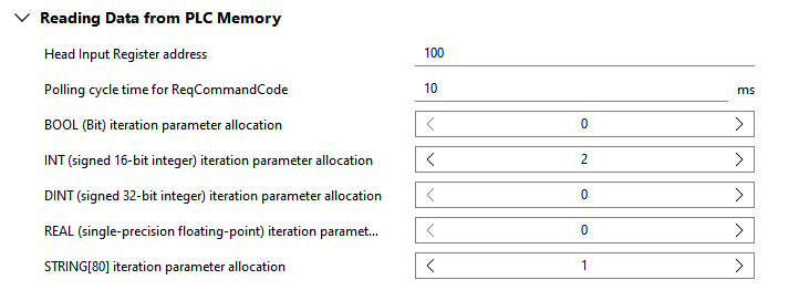
Head Input Register address
This parameter defines the first "Input Register Address" of the block that is reserved on the PLC. This block includes all values that are written by the PLC and read by the plug-in, for example, requested commands and values of iteration parameters. By default, it is set to 100 which corresponds to %MW100 on the PLC.
Alternatively, you can also set the parameter to a large number to minimize the chances of a memory overlap.
Polling cycle time for ReqCommandCode
This parameter defines the cycle time in which the value of the field "GMV_REQCOMMANDCODE" is read.
By default, it is set to 10 ms which means that the plug-in checks every 10 ms whether a new command is requested by the PLC.
BOOL (Bit) iteration parameter allocation
This parameter defines the number of iteration parameters of data type Boolean that can be transmitted from the PLC to MERLIC. For example, if you want to allow the PLC to override the Boolean values of up to five MVApp parameters defined in the recipe, set the parameter to at least 5.
By default, the parameter is set to 0 which means that no field will be added for any parameters of this data type.
Parameters of this data type require exactly 1 bit. Therefore, a single bit of a register address is mapped to the field of a Boolean parameters, up to 16 parameters. The individual iteration parameters within a given register are addressed using a hexadecimal digit, for example, %MW109:X0. If more than 16 Boolean parameters are defined, further register addresses are mapped to provide a field for each iteration parameter.
In addition, another field will be added: "GMV_ITPARAMUSEARRAY_BOOL_W0". This field is used by the PLC to indicate whether the provided parameter values in the recipe shall be overridden for the next execution by the values defined in the fields of the respective iteration parameters.
For each available iteration parameter of data type BOOL, the PLC needs to define bit by bit whether it should be used for the execution.
INT (signed 16-bit integer) iteration parameter allocation
This parameter defines the number of iteration parameters of data type INT that can be transmitted from the PLC to MERLIC. For example, if you want to allow the PLC to override the INT values of up to five MVApp parameters defined in the recipe, set the parameter to at least 5.
By default, the parameter is set to 0 which means that no field will be added for any parameters of this data type.
Parameters of this data type require exactly 16 bits which correspond to exactly one register address, for example, %MW110.
In addition, another field will be added: "GMV_ITPARAMUSEARRAY_INT_W0". This field is used by the PLC to indicate whether the provided parameter values in the recipe shall be overridden for the next execution by the values defined in the fields of the respective iteration parameters.
For each available iteration parameter of data type INT, the PLC needs to define bit by bit whether it should be used for the execution.
DINT (signed 32-bit integer) iteration parameter allocation
This parameter defines the number of iteration parameters of data type DINT that can be transmitted from the PLC to MERLIC. For example, if you want to allow the PLC to override the DINT values of up to five MVApp parameters defined in the recipe, set the parameter to at least 5.
By default, the parameter is set to 0 which means that no field will be added for any parameters of this data type.
Parameters of this data type require exactly 32 bits which correspond to exactly two register addresses. Therefore, two registers are reserved but only the address of the first will be mapped, for example, %MW111 if the addresses %MW111 and %MW112 are used.
In addition, another field will be added: "GMV_ITPARAMUSEARRAY_DINT_W0". This field is used by the PLC to indicate whether the provided parameter values in the recipe shall be overridden for the next execution by the values defined in the fields of the respective iteration parameters.
For each available iteration parameter of data type DINT, the PLC needs to define bit by bit whether it should be used for the execution.
REAL (single-precision floating-point) iteration parameter allocation
This parameter defines the number of iteration parameters of data type REAL that can be transmitted from the PLC to MERLIC. For example, if you want to allow the PLC to override the REAL values of up to five MVApp parameters defined in the recipe, set the parameter to at least 5.
By default, the parameter is set to 0 which means that no field will be added for any parameters of this data type.
Parameters of this data type require exactly 32 bits which correspond to exactly two register addresses. Therefore, two registers are reserved but only the address of the first will be mapped, for example, %MW113 if the addresses %MW113 and %MW114 are used.
In addition, another field will be added: "GMV_ITPARAMUSEARRAY_REAL_W0". This field is used by the PLC to indicate whether the provided parameter values in the recipe shall be overridden for the next execution by the values defined in the fields of the respective iteration parameters.
For each available iteration parameter of data type REAL, the PLC needs to define bit by bit whether it should be used for the execution.
STRING[80] iteration parameter allocation
This parameter defines the number of iteration parameters of data type STRING[80] that can be transmitted from the PLC to MERLIC. For example, if you want to allow the PLC to override the STRING_80 values of up to five MVApp parameters defined in the recipe, set the parameter to at least 5.
By default, the parameter is set to 0 which means that no field will be added for any parameters of this data type.
Parameters of this data type require exactly 80 bytes (640 bits) which corresponds to exactly 40 register addresses. They are mapped via a sequence of single WORDS, for example, %MW115 to %MW154, each corresponding to two bytes of ASCI characters. The symbols of the fields will be composed of several components. The first component is the prefix "GMV_ITPARAM_STRING80" which indicates that the field refers to an iteration parameter of data type STRING[80]. The second component is the index of the respective MVApp parameter. The third and last component is a suffix which is composed of the character "W" and an index number which indicates to which of the 40 registers, reserved for the STRING[80] parameter value, the respective field refers to. For example, the field with symbol "GMV_ITPARAM_STRING80_0_W0" references the first register address which is reserved for the first STRING[80] iteration parameter. Thus, it will be used for the value of the first two bytes of the first STRING[80] iteration parameter. The fields "GMV_ITPARAM_STRING80_0_W0" to "GMV_ITPARAM_STRING80_0_W39" then represent the WORDS reserved for the value of the first iteration parameter of data type STRING[80].
In addition, another field will be added: "GMV_ITPARAMUSEARRAY_STRING80_W0". This field is used by the PLC to indicate whether the provided parameter values in the recipe shall be overridden for the next execution by the values defined in the fields of the respective iteration parameters.
For each available iteration parameter of data type STRING[80], the PLC needs to define bit by bit whether it should be used for the execution.
Export Symbols
The parameters in this category define the location and name of the of the file that is exported with the global symbols when starting the plug-in. The file is based on the configuration of the plug-in and contains the global symbols for all fields that are to be reserved by the PLC. It contains some standard symbols that are always exported, for example, the symbols for requesting commands and also symbols of the fields for the number of results and iteration parameters that are defined in the configuration of the plug-in.
The file is formatted as a .csv file (comma-separated values file) and can be imported to the project of the PLC program.
The following image shows an overview of the parameters with the respective default setting. A detailed description of the parameters follows after the image.
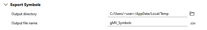
Output directory
This parameter defines the directory in which the file will be saved. You can select the directory from the file system via the ![]() button (on local systems) or you can type the path directly into the text field. By default, it is set to "%LOCALAPPDATA%/Temp" on Windows systems and to "/tmp" on Linux systems.
button (on local systems) or you can type the path directly into the text field. By default, it is set to "%LOCALAPPDATA%/Temp" on Windows systems and to "/tmp" on Linux systems.
Output file name
This parameter defines the name of the file. You can change the name directly in the text field. By default, it is set to "gMV_Symbols".
The file extension is automatically appended to the file name. If any other file extension is added manually, it is replaced with the compatible extension.
* Modicon® is a registered trademark of Schneider Electric USA, Inc.

