Tool Template "Check_Wafer"
This tool template is an example of a custom tool with basic functionality. It can be used as basis for the tool development of your own custom tool. The tool checks the quality of hazelnut wafers using a given gray value threshold. For this, the tool provides a tool parameter to set the threshold for the gray values. It also provides predefined types of ROIs which can be used to restrict the area to be processed and a parameter to connect alignment data of previous tools.
The tool template demonstrates how to define the desired types of ROIs that shall be supported for a tool and how to define parameters as additional tool parameters. You can also see how to set the colors for the visualization of an object and how to set the tool state of a custom tool.
Tool Procedures
The tool template demonstrates how a simple threshold tool can be created. It includes the following procedures which can be adopted to your use case.
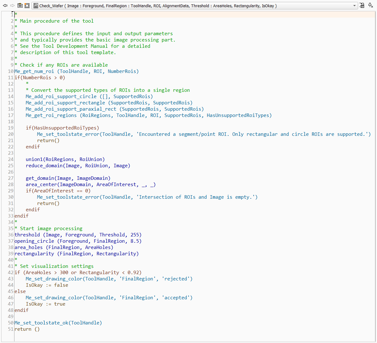
This procedure represents the main procedure of the tool, i.e., the execute procedure. It contains the basic image processing part of the custom tool. You may use this code as basis for your custom tool and adjust the implementation as required for your image processing task. In the following, we describe the code of the main procedure in more detail.
In the first part of the main procedure, the available ROIs are processed. For this, we start with querying the number of available ROIs using Me_get_num_roi. This way we can check in the if condition whether ROIs are available. If at least one ROI is available, the code within the if block is processed: The available ROIs of a predefined type are converted into regions. These regions are then unified to a single region. In case there is no intersection between the determined ROI region and the image, an error is returned. An error is also returned, if an ROI of an unsupported type is detected.
For the conversion of the ROIs, the interface procedure Me_get_roi_regions is used. It enables you to specify the ROI types that should be converted. The converted ROIs are returned in the output parameter "RoiRegions". In our example, we want to convert only paraxial rectangle ROIs, rectangle ROI, and circle ROIs. ROIs of other types, i.e., segment and point ROIs, will not be converted. In case such an unsupported ROI is available, the Boolean output parameter "HasUnsupportedRois" is set to 1. This parameter is then used to check whether an unsupported ROI is available. If this is the case, the tool state of the custom tool is set to an error and an error message is returned using the interface procedure Me_set_toolstate_error. The creation of the union of the converted regions and the intersection with the image domain is done with regular HALCON operators. However, for the error message that is returned if the ROI region does not intersect with the image, we use Me_set_toolstate_error again.
The next part of the main procedure implements the actual image processing task in which we determine the area in the image, i.e., the region, that fits to the given gray value threshold.
In the last part, the visualization of the final region is set using the interface procedure Me_set_drawing_color. This procedure can be used to set the color for a specific object either to predefined colors or to the default MERLIC colors that are defined the MERLIC preferences. In our example, we check the area of possible holes and the shape of the region in "FinalRegion" and set the color accordingly to the default MERLIC colors for "accepted" and "rejected" objects. This way, the region is visualized in the colors that are set in the MERLIC preferences and the MERLIC user has the possibility to change the colors if desired.
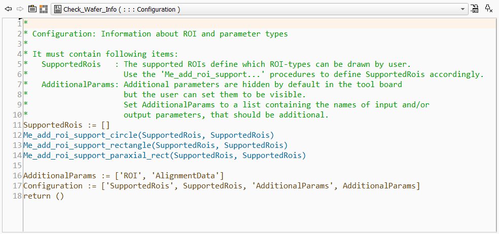
This procedure represents the _Info procedure of the tool. It is used to define which types of ROIs are supported for this tool. It also defines the additional tool parameters, i.e., parameters that are not visible by default at the tool board but can be accessed via the + button next to the other tool parameters. The "_Info" procedure returns the list of supported ROIs and additional parameters in a single output parameter "Configuration". Thus, it is required to collect the respective ROI types and additional parameter in this "Configuration" parameter.
The code of this example can be easily used as basis for the "_Info" procedure of your custom tool because the required adjustments will probably be only minimal.
In our example, the list of supported ROIs is defined by the interface procedures Me_add_roi_support_circle, Me_add_roi_support_rectangle, and Me_add_roi_support_paraxial_rect because we only want to support ROIs of these types. Each of these procedures add the respective ROI type to the ROI tuple in the parameter "SupportedRois". If you want to support also segment and point ROIs in your custom tool, you may use the respective interface procedures or even use the procedure Me_add_roi_support_all which defines the support of all ROI types. In our example, we use the same name for parameters containing the respective ROI tuple that is given as input and output of the procedure, i.e., "SupportedRois". You may also use different names but you have to ensure to provide the correct parameter to the subsequent code lines.
The list of additional parameters is simply defined as a tuple in the parameter "AdditionalParams". In our case, we want to set the "ROI" and "AlignmentData" parameter as additional. Thus, they are only visible on the tool board if the user adds them via the + button next to the other tool parameters.
Both, the list of supported ROIs and the list of additional parameters, are then used as input values for the "Configuration" parameter. This parameter expects a predefined structure as described in the documentation of the _Info procedure.
The use of the "_Info" procedure is optional. If you want to implement a custom tool without any ROI support and without any additional tool parameters and results, you don't have to use an "_Info" procedure. However, if you want to use any ROIs, additional tool parameters, or additional tool results in the custom tool, you have to specify the respective information in the "_Info" procedure.
Testing the Tool Template in HDevelop
The functionality of the custom tool can be tested directly in HDevelop with the provided test program "Check_Wafer_Test.hdev". The test program is located in the same directory as the procedure library representing the example tool, e.g., in "%PROGRAMFILES%\MVTec\MERLIC-26.03\examples\tool_development\tool_templates". This also enables you to make use of the debugging functionality in HDevelop.
If you use the provided tool template as basis for your own custom tool, you can also adjust the test program accordingly. This enables you to check the implemented features of your tool directly in HDevelop. If necessary, you can make further adjustments to ensure that the tool works as expected before integrating the custom tool in MERLIC.

