Determine Alignment with Matching
Use this tool to determine the alignment data based on a matching method.
This tool is used with a training mode. This means that first a training of the alignment data is performed with specified training parameters. The training starts automatically whenever training parameters are set or changed.
For this the tool provides a training area on the left of the Tool Board. It enables you to change between the processing mode to search and the training mode to train the alignment data by clicking on the respective image. The graphics window will display the image of the currently active mode which is highlighted in blue in the training area. In addition to the search parameters on the top left, the tool provides further parameters for the training on the top right of the tool.
See the topic Working with the Training Mode to learn more about how to work with tools that require a training.
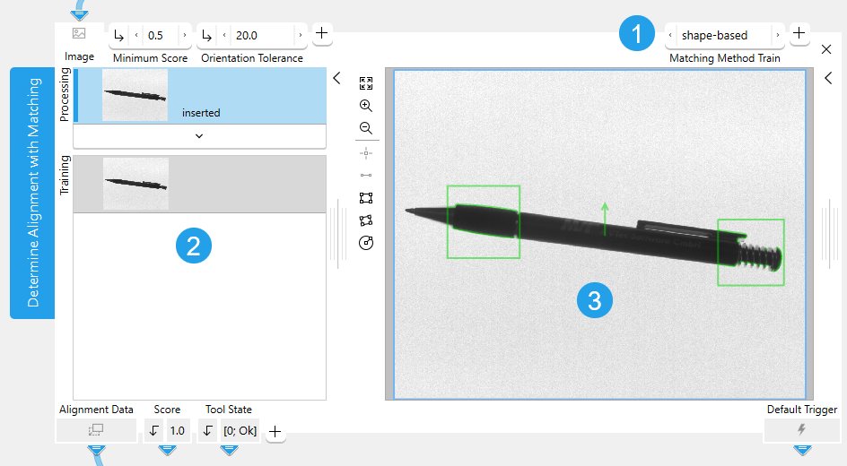
![]() Training parameters
Training parameters
![]() Training area
Training area
![]() Graphics window
Graphics window
Defining the Training Settings
Selecting the Training Image
For this tool only one image can be used as training image. When the tool is inserted, the current processing image is automatically used as training image. You may also change the training image with the following steps:
- Run the application in single steps until the desired image is displayed in the graphics window and thus in the "Processing" area.
- Click on the
 button in the training area on the left to replace the current training image with the image from the "Processing" area. The training mode is automatically activated and the new training image is displayed in the graphics window.
Selecting the Matching Model
For this tool easyTouch and easyTouch+ are available. This means you may select the matching model for the alignment interactively as follows:
- Click on the training image on the left of the Tool Board. The training image will be displayed in the graphics window and you may start with the selection of the matching model.
- Move the mouse over the image to display a preview of regions of interest (ROI) for the model. Alternatively draw a model ROI using the ROI selection buttons. When using easyTouch to select the model, the color of the previewed model ROI is an indicator for the suitability of the ROI, i.e., of the object inside the rectangle, for the training. The accuracy, the scale, and the rotation invariance depend on the contrast, the size, and the shape of the underlying object. The meaning of the different colors is as follows:
- A potentially good model ROI is highlighted in the color defined for "accepted", e.g., green by default.
- If the model ROI is highlighted in the color defined for "warning", e.g., yellow by default, it might not be the best for the training, e.g., due to missing or too few model edges.
- A bad model ROI is highlighted in the color defined for "rejected", e.g., red by default. If the rectangle is very close to the image border, it is visualized in red because the object may only be partially visible in the processing images.
- If you want to use the highlighted ROI for the alignment, click on the ROI to confirm the selection. The corresponding training parameters are determined automatically.
To increase the robustness of the training with respect to rotation variations, we recommend to select two different model ROIs and thus train a matching model with two ROIs that are at best on opposite sides of the image.
Defining the Search Settings
Adjusting the Search Parameters
In contrast to the training parameters, the search parameters on the left side are not automatically adjusted. They depend on the images of your application and should be adjusted accordingly.
You can check if the current settings of the training and search parameters are suitable. Run the application with a series of images and you can instantly check in the graphics window if the trained matching model is correctly found in the images. If necessary, you can make further adjustments at the parameters.
Area Restrictions
The objects are searched within an area that is determined by the "Processing Region" and the ROI. An object is returned, if its center of gravity lies inside of this search area. In case the center of gravity lies outside of the objects the search area should be adjusted thus that the search area includes the center of gravity. This ensures that the object is found. Objects, which lie partially outside of the image, will be ignored during the processing.
Parameters
Basic Parameters
Image:
This parameter represents the input image used for the processing of this tool. It can be used either as a training image to determine the "Alignment Data" or it can be used as a processing image to test the determined "Alignment Data" and the current parameter setting for the training.
If a color image is used as input image for this tool, only the first channel, i.e., the red channel, is used for the processing.
Minimum Score:
This parameter defines how accurate the matching is done. It is used for the search of the model and determines how much of the trained model must be visible in the image to find a matching object. It is set to 0.5 by default. This means that half of the model may be occluded in the image. You can change its value at the corresponding connector. The value can be set to a number between 0.1 and 1. The higher the "Minimum Score" the faster is the search. If the model can be expected never to be occluded in the images, the "Minimum Score" may be set as high as 0.8 or even 0.9. Otherwise you may have to decrease the value of this parameter to find matches in images in which a big part of the trained model is occluded.
To speed up the search, a so-called pyramid of contracted images is used. A match needs a score that is large enough on every level to be recognized as such. This can lead to excluding matches, although their score on the original image is larger than the minimal score, because they are not recognizable enough on a higher contraction level. These missed matches may be found with a lowered minimum score.
You may test the current "Minimum Score" by running the application step by step and check if the presence of the objects is checked correctly within all images.
Orientation Tolerance:
This parameter defines the tolerance value for the rotation of the matching model. It is used for the search of the model and determines how much the rotation of possible matches in the search images may differ from the rotation of the model in the training image. It is defined in degrees and set to 20° by default. You can change the "Orientation Tolerance" to an angle between 0° and 180° at the corresponding connector. If the rotation range in which the models appear in the search images is known, you can adjust the value of the "Orientation Tolerance" accordingly.
Additional Parameters
ROI:
This parameter defines the region of interest (ROI) for processing. Image parts outside of the union of the ROI and "Processing Region" are not processed.In addition, if either of them is empty, the image part inside of the other one is processed. In case both of them are empty, the whole image is processed.
By default the ROI is defined as an empty ROI. If you want to use a non-empty ROI for the processing, you either have to connect the parameter to an appropriate ROI result of a previous tool or you have to draw new ROIs into the image using the available ROI buttons. If you are using an ROI result of a previous tool, you can also draw additional ROIs using the ROI buttons.
The union of the defined ROI and the "Processing Region" is used as search area for the trained model. It may be sufficient if only a part of the trained model, e.g., only one of two model ROIs, lies within the search area to find a match. However, if the trained model lies outside of this area, it is not found.
Deformation Tolerance:
This parameter defines the maximum allowable deformation of the object. It is defined in pixels and set to 1 px by default. This means that objects that are deformed up to 1 px with respect to the shape of the trained model are also found. You can change its value at the corresponding connector to an integer value between 0 and 5 px and above if you enter the value manually. If you set the value to 0 px, only objects without any deformations are found. However, the higher the "Deformation Tolerance" the higher is the risk that wrong objects are found, especially for objects with fine structures.
The "Deformation Tolerance" should therefore be chosen as small as possible and only as high as necessary. If it is known how much deformation of the model may be expected in the images, you can adjust the value for the "Deformation Tolerance" accordingly. The "Deformation Tolerance" only is valid if "Matching Method Train" is set to "shape-based".
Size Tolerance:
This parameter defines a tolerance value for the size of the matching model. It is defined in pixels and set to 0 px by default. This means that the model must have the same size in the images as the trained model to be classified as a match. You can change the "Size Tolerance" at the corresponding connector to an integer value between 0 and 20 px. The "Size Tolerance" only is valid if "Matching Method Train" is set to "shape-based".
Processing Region:
This parameter defines the region for processing. Image parts outside of the union of the ROI and "Processing Region" are not processed. In addition, if either of them is empty, the image part inside of the other one is processed. In case both of them are empty, the whole image is processed.
By default, "Processing Region" is defined as empty region. To specify a "Processing Region", you have to connect the parameter to an appropriate region result of a previous tool to make sure that a region is transmitted to this tool.
If easyTouch is used to select the matching model, the whole image is used for the processing. This means that depending on the settings of e.g., "Orientation Tolerance" the trained model will be found in a different position in the processing image.
Training Parameters
Basic Training Parameters
Matching Method Train:
This training parameter defines the matching method that is used for the determination of the training model. The parameter is set to "shape-based" by default. You can change the Matching Method Train at the corresponding connector.
|
Value |
Description |
|---|---|
|
shape-based |
This matching approach describes the trained model by the shapes of its contours. Use this method, if you want to determine the "Alignment Data" with a matching method that finds the best matches of a shape model in an image. |
|
correlation-based |
This matching approach describes the trained model by the gray value relations of the contained pixels. Use this method, if you want to determine the "Alignment Data" with a matching method that uses normalized cross correlation (NCC) to match objects or patterns. |
Additional Training Parameters
The additional training parameters are listed by the matching method they are related to. Parameters of other methods will have no influence on the resulting training model.
This training parameter defines the edge contrast of the used model. It is defined in gray values and set to 10 by default. This means that objects with a contrast of at least 11 gray values will be found. There are different ways to set the edge contrast:
- Automatically with easyTouch
Use easyTouch to select the objects in the training image. The parameter value is automatically adjusted according to your easyTouch selection.
- Automatically using the region of interests (ROIs)
Set the edge contrast manually to 0 at the connector and draw a model ROI over each part in the training image in which you want to find reference objects. The tool automatically detects all possible objects with any contrast. If you want to add further objects as reference for the training, you have to make sure to draw the model ROI manually into the image. The parameter value at the connector remains 0 until you change the value manually or use easyTouch.
- Manually
Set the desired edge contrast manually at the corresponding connector and draw a model ROI over each part in the training image in which you want to find reference objects. You can set the value with the slider or type a value between 1 to 1 000 000 000 into the text field. All possible objects that fit to the defined edge contrast will be found. If you want to add further objects as reference for the training, you have to make sure to draw the model ROI manually into the image. When using easyTouch to select the objects, the parameter value is adjusted automatically and your previously defined setting will be lost.
This training parameter defines the edge contrast that is used for the search of the objects in the training images. It is defined in gray values and set to 5 by default. This means that objects with a contrast of at least 6 gray values will be found. There are different ways to set the edge contrast:
- Automatically witheasyTouch
Use easyTouch to select the objects in the training image. The parameter value is automatically adjusted according to your easyTouch selection.
- Automatically using the region of interests (ROIs)
Set the edge contrast manually to 0 at the connector and draw a model ROI over each part in the training image from which the edge contrast shall be determined and used for the search. The tool automatically detects all possible objects with any contrast. If you want to add further objects as reference for the edge contrast, you have to make sure to draw the model ROI manually into the image. The parameter value at the connector remains 0 until you change the value manually or use easyTouch.
- Manually
Set the desired edge contrast manually at the corresponding connector and draw a model ROI over each part in the training image in which you want to determine the edges with the defined contrast. You can set the value with the slider or type a value between 1 to 1 000 000 000 into the text field. All possible objects that fit to the defined edge contrast will be found. If you want to add further objects as reference for the training, you have to make sure to draw the model ROI manually into the image. When using easyTouch to select the objects, the parameter value is adjusted automatically and your previously defined setting will be lost.
This parameter defines the number of pyramid levels used during the search. The parameter is set to "auto" by default. The "Highest Pyramid Level" is determined automatically by easyTouch when a model ROI has been selected in the training image. You can also change its value manually at the corresponding connector to a level between 2 and 8. It should be set as large as possible to reduce the time needed to find the object. However, if it is set too large, the model may not be recognized anymore. Thus it should also be set small enough that the model is still recognizable.
The selection of the suitable pyramid level, i.e., the highest pyramid level on which at least one instance of the shape model can be found, depends on the model and on the input image. The appropriate "Highest Pyramid Level" may vary from image to image. If the input image is of poor quality, i.e., the image is defocused, deformed, or noisy, it may be possible that no instance of the model is found with the default setting because of possibly missing or deformed edges. In this case decrease the value for the "Highest Pyramid Level".
If the parameter "Highest Pyramid Level" is set too small, the time required to find the model may increase and cause MERLIC to be very slow. This is especially the case if images with a large size are used. In this case we recommend to increase the value for "Highest Pyramid Level".
This training parameter defines the minimum length of the used model edges. It is defined in pixels and set to 5 px by default. There are different ways to determine the length of the edges:
- Automatically with easyTouch
Use easyTouch to select the objects in the training image. The parameter value is automatically adjusted according to your easyTouch selection.
- Automatically using the region of interests (ROIs)
Set the edge contrast manually to 0 at the connector and draw a model ROI over each part in the training image in which you want to determine the minimum length of edges for the training. The tool automatically detects the minimum length of all possible edges. If you want to add further objects for the training, you have to make sure to draw the model ROI manually into the image. The parameter value at the connector remains 0 until you change the value manually or use easyTouch.
- Manually
Set the desired edge length manually at the corresponding connector and draw a model ROI over each part in the training image in which you want to find edges with the defined length. This enables you to define that only model edges with the specified minimum length are included in the training. You can set the value with the slider or type a value between 1 to 1 000 000 000 px into the text field. If you want to add further objects for the training, you have to make sure to draw the model ROI manually into the image. When using easyTouch to select the objects, the parameter value is adjusted automatically and your previously defined setting will be lost.
The parameter determines the conditions under which the model is recognized in the image. It is set to "use polarity" by default.
|
Value |
Description |
|---|---|
|
use polarity |
If this polarity metric is used, the object in the training image and the processing image must have the same contrast, e.g., if the model is a bright object on a dark background, the object is found only if it is also brighter than the background. This metric can only be applied to single-channel images. If a multichannel image is used as the training image or as the processing image, only the first channel will be used. |
|
ignore color polarity |
If this polarity metric is used, the model is found even if the color contrast changes locally, e.g., if parts of the object change their color from green to red. This mode is useful if you do not know in advance in which channels the object is visible. However, the run time in the processing mode can increase significantly with this polarity metric. This metric can be used for images with an arbitrary number of channels. If it is used for single-channel images, it has the same effect as "ignore local polarity". The number of channels in the creation of the training model and the search can be different. This can be used to create a model from a synthetically generated single-channel image. Furthermore, the channels do not need to contain a spectral subdivision of the light like in an RGB image. The channels can also contain images of the same object that were obtained by illuminating the object from different directions. |
|
ignore global polarity |
If this polarity metric is used, the model is found in the image also if the contrast reverses globally, e.g., if the model is a bright object on a dark background, the object is not only found if it is brighter than the background (as for "use polarity") but also if it is darker than the background. In this case, the run time in the processing mode will increase slightly. This metric can only be applied to single-channel images. If a multichannel image is used as the training image or as the processing image, only the first channel will be used. |
|
ignore local polarity |
If this polarity metric is used, the model is found even if the contrast changes locally. This is useful if the object consists of a part with medium gray value, within which either darker or brighter sub-objects lie. However, the run time in the processing mode can increase significantly with this polarity metric. This metric can only be applied to single-channel images. If a multichannel image is used as the training image or as the processing image, only the first channel will be used. |
This parameter defines the number of pyramid levels used during the search. The parameter is set to "auto" by default. The "Highest Pyramid Level" is determined automatically by easyTouch when a model ROI has been selected in the training image. You can also change its value manually at the corresponding connector to a level between 2 and 8. It should be set as large as possible to reduce the time needed to find the object. However, if it is set too large, the model may not be recognized anymore. Thus it should also be set small enough that the model is still recognizable.
The selection of the suitable pyramid level, i.e., the highest pyramid level on which at least one instance of the shape model can be found, depends on the model and on the input image. The appropriate "Highest Pyramid Level" may vary from image to image. If the input image is of poor quality, i.e., the image is defocused, deformed, or noisy, it may be possible that no instance of the model is found with the default setting because of possibly missing or deformed edges. In this case decrease the value for the "Highest Pyramid Level".
If the parameter "Highest Pyramid Level" is set too small, the time required to find the model may increase and cause MERLIC to be very slow. This is especially the case if images with a large size are used. In this case we recommend to increase the value for "Highest Pyramid Level".
The parameter determines the conditions under which the model is recognized in the image. It is set to "use polarity" by default.
|
Value |
Description |
|---|---|
|
use polarity |
If this polarity metric is used, the object in the training image and the processing image must have the same contrast, e.g., if the model is a bright object on a dark background, the object is found only if it is also brighter than the background. This metric can only be applied to single-channel images. If a multichannel image is used as the training image or as the processing image, only the first channel will be used. |
|
ignore color polarity |
If this polarity metric is used, the model is found even if the color contrast changes locally, e.g., if parts of the object change their color from green to red. This mode is useful if you do not know in advance in which channels the object is visible. However, the run time in the processing mode can increase significantly with this polarity metric. This metric can be used for images with an arbitrary number of channels. If it is used for single-channel images, it has the same effect as "ignore local polarity". The number of channels in the creation of the training model and the search can be different. This can be used to create a model from a synthetically generated single-channel image. Furthermore, the channels do not need to contain a spectral subdivision of the light like in an RGB image. The channels can also contain images of the same object that were obtained by illuminating the object from different directions. |
|
ignore global polarity |
If this polarity metric is used, the model is found in the image also if the contrast reverses globally, e.g., if the model is a bright object on a dark background, the object is not only found if it is brighter than the background (as for "use polarity") but also if it is darker than the background. In this case, the run time in the processing mode will increase slightly. This metric can only be applied to single-channel images. If a multichannel image is used as the training image or as the processing image, only the first channel will be used. |
|
ignore local polarity |
If this polarity metric is used, the model is found even if the contrast changes locally. This is useful if the object consists of a part with medium gray value, within which either darker or brighter sub-objects lie. However, the run time in the processing mode can increase significantly with this polarity metric. This metric can only be applied to single-channel images. If a multichannel image is used as the training image or as the processing image, only the first channel will be used. |
Results
Basic Results
Alignment Data:
This result returns the trained alignment data needed for the alignment of the images.
Score:
This result returns a numeric value that indicates how much the found object matches the trained model that is searched. The result is returned as a real number between 0 and 1. If the "Score" has the value 1, the found object matches the trained model with an accuracy of 100%.
Tool State:
"Tool State" returns information about the state of the tool and thus can be used for error handling. For more information, see Tool State Result
Additional Results
Model Edges:
This result returns the contour of the trained model edges.
Orientation Arrow:
This result returns the arrow that indicates the orientation of the model ROI that has been used for the training. It is returned in form of a contour.
Processing Time:
This result returns the duration of the most recent execution of the tool in milliseconds. The result is provided as additional result. Therefore, it is hidden by default but it can be displayed via the ![]() button beside the tool results. For more information see the section Processing Time in the tool reference overview.
button beside the tool results. For more information see the section Processing Time in the tool reference overview.
Application Examples
This tool is used in the following MERLIC Vision App examples:
- adapt_brightness_for_measuring.mvapp
- check_bent_leads.mvapp
- check_pen_parts.mvapp
- check_saw_angles.mvapp
- check_single_switches.mvapp
- detect_anomalies_of_bottles.mvapp
- determine_circle_quality.mvapp
- measure_distance_to_center_led.mvapp
- read_best_before_date_with_orientation.mvapp
- read_text_in_3d_height_image.mvapp

