Measure Circle
Use this tool to measure one or more circles.
For this tool easyTouch and easyTouch+ are available. This means you may select the circles to be measured interactively in the image while the corresponding parameters are automatically adapted. Move the mouse pointer over the edge of the circle to be measured. MERLIC will display a preview of a suggested circle. If you want to measure the previewed circle, click on the circle edge to confirm the selection. The parameters are automatically adjusted to fit the selected circle. However, they still can be adjusted manually at the corresponding connectors.
To add further circles to the measurement, you can use easyTouch+, i.e., by pressing the Ctrl key and selecting the additional circle. MERLIC automatically checks if the selected circle fits to the current parameter settings of the previous selection. If they do not fit, e.g., because the mouse hovers over a circle with an opposite edge transition, MERLIC gives immediate feedback in the image. In this case, it is still possible to add the circle to the measurement but the parameter settings will be adjusted accordingly.
Alternatively, you may use regions of interest (ROIs) for the measuring. Draw an ROI into the image or connect the parameter "ROI" to the result of a previous tool. If the ROI samples out a circle in the image that fits the current parameter settings, it is automatically determined and measured.
Parameters
Basic Parameters
Image:
This parameter represents the input image in which the circle is measured.
If a color image is used as input image for this tool, only the first channel, i.e., the red channel, is used for the processing.
Edge Contrast:
This parameter defines the contrast of the circle edge relative to the background. It is defined in gray values and set to 20 by default. When a circle is selected for the measuring, the "Edge Contrast" of this circle is instantly determined and adopted. If further circles are added using easyTouch+, the "Edge Contrast" is adjusted automatically with each circle that is added to the selection. However, you may also change its value manually at the corresponding connector.
Edge Width:
This parameter defines the width of the circle edge. It is defined in pixels and set to 1 px by default. When a circle is selected for the measuring, the "Edge Width" of this circle is instantly determined and adopted. If further circles are added using easyTouch+, the "Edge Width" is adjusted automatically with each circle that is added to the selection. However, you may also change its value manually at the corresponding connector.
Edge Transition:
This parameter defines the transition property of the circle edge. The transition is determined from inside to outside. The parameter is set to "light to dark" by default. When a circle is selected for the measuring, the "Edge Transition" is instantly determined and adjusted automatically for each circle that is added to the selection.
|
Value |
Description |
|---|---|
|
light to dark |
The edge of the circle changes from light to dark, i.e., the edge changes from higher to lower gray values. If this value is set, only circles with this transition property are measured. Other circles are excluded from the measurement. |
|
dark to light |
The edge of the circle changes from dark to light, i.e., the edge changes from lower to higher gray values. If this value is set, only circles with this transition property are measured. Other circles are excluded from the measurement. |
|
any |
The edge of the circle may change in either direction, i.e., the edge may change from higher to lower gray values or from lower to higher gray values. If this value is set, all circles are included in the measurement. |
Additional Parameters
ROI:
This parameter defines the region of interest (ROI) for the processing. By default ROI is defined to be empty. If you want to use an ROI for the processing, you either have to connect the parameter to an appropriate ROI result of a previous tool or you have to draw new ROIs into the image using the ROI button ![]() .
.
The defined circle ROI is checked if it corresponds to a circle in the image that fits to the current parameter settings, e.g., if the "Edge Transition" is set to "dark to light", the tool checks if the edge of the circle changes from dark to light. If suitable circles are found in the ROI, they are used for the measurement.
Calibration Data:
This parameter defines the calibration data needed for the correction of possible lens distortions and the position of the camera with respect to the image plane. By default no calibration data are defined. If you want to use calibration data, you have to connect the parameter to an appropriate result of a previous tool, e.g., Calibrate Camera, to make sure that the calibration data are transmitted to this tool. It will be instantly applied to the image.
In case "Calibration Data" are used for this tool, all results that represent pixel values will be automatically transformed to the corresponding world coordinates.
Alignment Data:
This parameter represents the alignment data that are used to align the ROI. By default no alignment data are connected and thus no effect is visible. If you want to use specific alignment data, you have to connect the parameter to an appropriate result of a previous tool such as Determine Alignment with Matching, Determine Alignment with Straight Border, Align Image, or Rotate Image.
Radius Tolerance:
This parameter defines the tolerance value for the allowed radii of the individual circle segments. It can also be interpreted as an indicator to the circularity of the circles to be measured. When the mouse is moved over the edge of a circle segment MERLIC searches for further circle segments that could complete the individual segments to a circle. The "Radius Tolerance" defines the tolerance value how much the radii of these circle segments may differ from the circle segment that has been selected with the mouse. Thus, if you want to measure circles with a high shape quality, i.e., a high circularity, we recommend to you set a low "Radius Tolerance" and vice versa.
The parameter is defined in pixels and set to 10 px by default. This means, that the individual circle segments may have a radius that differs up to 10 px from the radius of the selected circle edge. Circles that do not fulfill this condition will not be suggested in the preview of easyTouch.
Minimum Edge Completeness:
|
Visualization |
Description |
|---|---|
|
|
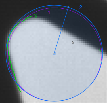
This parameter defines the minimum fraction of the circle (1) that has to be supported by the contours (2) detected along the ROI (3). If the detected contours account for less than the "Minimum Edge Completeness" as percentage of the circle circumference, MERLIC will not establish a circle. In this case neither the contour nor the circle will be displayed. The contours used for determining the "Minimum Edge Completeness" are detected along the whole edge of the ROI and may also include undesired contour segments as shown in the image on the left. The "Minimum Edge Completeness" is defined as a value between 0 and 1 and can be interpreted as a percentage value from 0% to 100%. It is set to 0.5 by default. An applicable value is automatically determined by easyTouch when an edge is selected. However, you may also adjust the parameter value manually, if you only want to use circles with a specific "Minimum Edge Completeness". |
Failed Measurement:
This parameter defines which value is returned in the result "Radius", "X", "Y", "Edge Completeness", and "Shape Quality" in case no measurement could be performed. The parameter is set to "ignore" by default.You may set the parameter at the corresponding connector to the following values.
|
Value |
Description |
|---|---|
|
ignore |
No value is returned if no measurement could be performed. |
|
−1 |
−1 is returned if no measurement could be performed. You may replace it directly in the input field of the connector with any number or string you want to return. |
|
* |
* is returned if no measurement could be performed. You may replace it directly in the input field of the connector with any number or string you want to return. |
Results
Basic Results
Circle:
This result returns the graphical representation of the circle that has been measured. It is returned as a circular ROI. If more than one circle has been measured, "Circle" contains the ROIs of all circles.
Radius:
This result returns the radius of the measured circle(s). The result is returned in pixels as a real number. If more than one circle is measured, the corresponding radii are returned in a tuple.
Shape Quality:
This result returns a rating of the circle's shape. It is returned as a percentage value in real numbers between 0 and 1. The higher the value the rounder is the shape of the measured circle. A "Shape Quality" of 1 means that the circle has a perfect round shape. If more than one circle is measured, the corresponding "Shape Quality" values are returned in a tuple.
Tool State:
"Tool State" returns information about the state of the tool and thus can be used for error handling. Please see the topic Tool State Result for more information about the different tool state results.
Additional Results
X:
This result returns the position of the center point for the measured circle in X direction. It is returned in pixel coordinates. In case "Calibration Data" is used, the position is returned in world coordinates. If more than one circle is measured, the corresponding x-coordinates are returned in a tuple.
Y:
This result returns the position of the center point for the measured circle in Y direction. It is returned in pixel coordinates. In case "Calibration Data" is used, the position is returned in world coordinates. If more than one circle is measured, the corresponding y-coordinates are returned in a tuple.
Edge Completeness:
This result contains the actual "Edge Completeness" of the measured circle. It is returned as a percentage value in real numbers between 0 and 1. It is an indicator for how much of the contour points of the circle edge could be used for the measurement. If more than one circle is measured, the corresponding "Edge Completeness" values are returned in a tuple.
Used Edges:
This result returns the contour of the edges that have been used for the measurement. The returned contour in "Used Edges" might differ from the actual edges in the image, especially when the ROI is very small.
Processing Time:
This result returns the duration of the most recent execution of the tool in milliseconds. The result is provided as additional result. Therefore, it is hidden by default but it can be displayed via the ![]() button beside the tool results. For more information see the section Processing Time in the tool reference overview.
button beside the tool results. For more information see the section Processing Time in the tool reference overview.
Application Examples
This tool is used in the following MERLIC Vision App examples:
- adapt_brightness_for_measuring.mvapp
- determine_circle_quality.mvapp
- measure_distance_segment_circle_calibrated.mvapp

