Read QR Code
Use this tool to detect and read one or more codes of the type QR or Micro QR in an image. If the tool is added, the current processing image is automatically scanned and by default the first regular QR code on it is read.
Training
This tool is used with a training mode. easyTouch and easyTouch+ can be used to estimate values in the current image in the processing mode. This may be useful to find out, whether the codes in the image can be read at all. The training mode should then be used to determine the best parameter settings with a series of images.
- Run the application step by step via the "Run Once" button or via the shortcut F6 until an image is shown that you want to use as training image.
- Add the current image to the set of training images by clicking on the
 button or by using the shortcut F3. The tool automatically highlights the possible contours of the codes in the images.
 - If necessary, draw an ROI over the code.
- To add further training images, repeat the previous steps again.
- Click on the "Apply training data" button to perform the training. The parameters for the set of training images are automatically determined. In addition, the tool automatically switches to the processing mode and shows the detected codes in the current image.
Check the training
- Click on the processing image to switch to the processing mode.
- Run MERLIC with a series of images to check whether the codes are detected and read.
- To check the decoded data of a specific code, move the mouse pointer over the code in the image. The decoded data will be instantly shown in a tooltip. Alternatively, you can also check the decoded data in the respective tool result.
You can restrict the area for the data code detection. Draw an ROI over the image part in which you want to read codes and add the image as training image. The codes are now only read in the defined image part.
Tool Structure
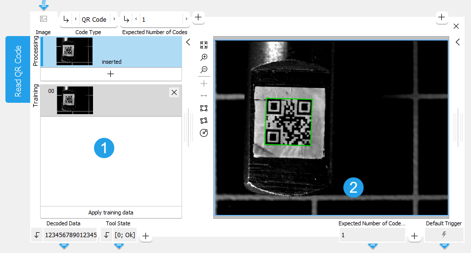
The Tool Board is split into the training area on the left of the and the graphics window on the right.
![]() Training area
Training area
![]() Graphics window
Graphics window
The first image on the left side of the Tool Board shows the image that is currently loaded. At this stage MERLIC already provides a preview of all found codes and already provides results if the reading was successful with the default parameter settings.
You have to select the training image by clicking on the ![]() button to transfer the image shown in "Processing" to the "Training" area. You can also add an additional image. To do so, run the program in single steps until the image you want to use as training image is shown in "Processing" and press the
button to transfer the image shown in "Processing" to the "Training" area. You can also add an additional image. To do so, run the program in single steps until the image you want to use as training image is shown in "Processing" and press the ![]() button. In any case, press the button "Apply training data" to adapt the parameters to the training image.
button. In any case, press the button "Apply training data" to adapt the parameters to the training image.
The parameters can then be tested with further images within the same tool. See the topic Working with the Training Mode to learn more about how to work with tools that require a training.
Parameters
Depending on the selected code type at the parameter "Code Type" and/or the selected value at the parameter "Conform to Standard", some connectors are grayed out. This means that they are not applicable for the currently selected parameters and thus have no effect.
Basic Parameters
Image:
This parameter represents the image in which the QR Code should be read.
If a color image is used as input image for this tool, only the first channel, i.e., the red channel, is used for the processing.
Code Type:
Select which code types should be detected and decoded in the image.
|
Value |
Description |
|---|---|
|
QR Code |
Detect and read codes of the type QR. The finder element of a QR Code consists of three squares, which are called position detection patterns. |
|
Micro QR Code |
Detect and read codes of the type Micro QR. The smaller Micro QR Code has only one finder pattern which is also square shaped. |
Expected Number of Codes:
This parameter defines the expected number of codes present in the image. As a default, this value is set to 1. If less codes are found than the expected number, the code reading fails. Due to the image processing that is in use, it is possible that the tool will find more than the minimum expected number of codes. In this case use an ROI to restrict the area of the data code detection.
Additional Parameters
Processing Region:
This parameter defines the region for processing. Image parts outside of the union of the ROI and "Processing Region" are not processed. In addition, if either of them is empty, the image part inside of the other one is processed. In case both of them are empty, the whole image is processed.
By default, "Processing Region" is defined as empty region. To specify a "Processing Region", you have to connect the parameter to an appropriate region result of a previous tool to make sure that a region is transmitted to this tool.
If easyTouch is used to determine the parameters values, the whole image is used for the search.
ROI:
The parameter "ROI" defines the region of interest (ROI) for the code detection. Image parts outside of the union of the "ROI" and the "Processed Region" are not processed.In addition, if either of them is empty, the image part inside of the other one is processed. In case both of them are empty, the whole image is processed. However, if easyTouch is used to determine the parameter values, the whole image is used for the processing.
By default the ROI is defined as an empty ROI. If you want to use a non-empty ROI for the processing, you either have to connect the parameter to an appropriate ROI result of a previous tool or you have to draw new ROIs into the image using the available ROI buttons.
If easyTouch is used to determine the parameters values, the whole image is used for the search.
Alignment Data:
This parameter represents the alignment data that are used to align the ROI. By default no alignment data are connected and thus no effect is visible. If you want to use specific alignment data, you have to connect the parameter to an appropriate result of a previous tool such as Determine Alignment with Matching, Determine Alignment with Straight Border, Align Image, or Rotate Image.
Timeout:
By using this parameter, it is possible to interrupt the execution of the tool after a defined period in milliseconds. This is especially useful in cases where a maximum cycle time has to be ensured. The temporal accuracy of this interrupt is about 10 ms. The accuracy depends on several factors including the speed of your computer. The timeout is ignored in training mode. The default timeout is 0 ms.
|
Value |
Description |
|---|---|
|
0 |
As a default, no timeout is set. |
|
1 - 1000 |
This is the available value range for setting the timeout in milliseconds. |
Contrast Tolerance:
This parameter defines the tolerance of the search with respect to local contrast variations, for example, in the presence of glare or reflections. Depending on the value of the parameter, two different algorithms are applied. The default setting is "low".
|
Value |
Description |
|---|---|
|
low |
Fast algorithm: This setting is useful if few local contrast variations are present. It is less robust in case of strong local contrast variations. |
|
high |
Robust but slower algorithm: This setting is useful if strong local contrast variations are present. |
|
any |
Strong contrast variations may or may not be present. Both algorithms are applied. |
Minimum Contrast:
This parameter is deactivated because it has no longer any effect due to the underlying HALCON version. It is only retained for compatibility reasons.
Mirrored Code:
This parameter describes whether the symbol is or may be mirrored which is equivalent to swapping rows and columns of the symbol. The default setting is "no".
|
Value |
Description |
|---|---|
|
no |
The code does not appear mirrored. |
|
yes |
The code always appears mirrored. |
|
any |
The code may appear mirrored. |
Minimum Gap Width
This parameter defines the minimum gap width in direction of the symbol rows and columns. The default setting is "no".
|
Value |
Description |
|---|---|
|
no |
There is no minimum gap width. |
|
small |
The gap width is at least small. |
|
big |
The gap width is big. |
Maximum Gap Width
This parameter defines the maximum gap width in direction of the symbol rows and columns. The default setting is "small".
|
Value |
Description |
|---|---|
|
no |
There is no maximum gap width. |
|
small |
A small gap is allowed. |
|
big |
A big gap is allowed. |
Minimum Module Size:
This parameter specifies the minimum size of the modules in the image. It is defined in pixels and set to 6 px by default.
|
Value |
Description |
|---|---|
|
6 |
This is the default minimum module size. All symbols with a module size higher than 6 pixels can potentially be read. |
|
1 - 100 |
This is the available value range for setting the minimum module size. |
Maximum Module Size:
This parameter specifies the maximum size of the symbol modules. It is defined in pixels and set to 20 px by default.
|
Value |
Description |
|---|---|
|
20 |
This is the default maximum module size. All symbols with a module size up to 20 pixels can potentially be read. |
|
6 - 100 |
This is the available value range for setting the maximum module size. |
Code Property:
The parameter determines if the symbol appears dark on a light background or light on a dark background. The default setting is "dark".
|
Value |
Description |
|---|---|
|
dark |
This is the default setting. The symbol appears dark on a light background. |
|
light |
The symbol appears light on dark background. |
|
any |
The symbol may appear either dark on light background or light on dark background. |
Minimum Number of Position Patterns:
This parameter represents the number of position detection patterns that have to be visible for generating a new symbol candidate. This value can only be changed if "QR Code" was selected as "Code Type". The parameter is not applicable and thus grayed out if "Micro QR Code" is selected as "Code Type". It is set to 2 by default.
|
Value |
Description |
|---|---|
|
2 |
This is the default value for the number of position patterns that have to be visible. All symbols with at least 2 visible position patterns can potentially be read. |
|
2 - 3 |
This is the available value range for setting the minimum number of position patterns. |
Robust Against Small Modules:
This parameter defines the robustness of the decoding of data codes with very small module sizes. Setting the parameter "Robust Against Small Modules" to 1, which is high, increases the likelihood of being able to decode data codes with very small module sizes. Additionally, in that case the minimum module size should also be adapted accordingly. Setting "Robust Against Small Modules" to 1 can significantly increase the internal memory usage of the tool. Therefore the default setting is 0, which means low.
|
Value |
Description |
|---|---|
|
0 |
This is the default setting. Use this setting for a low robustness against small modules. |
|
1 |
Us this setting if a high robustness against small modules is required. This setting increases the memory usage. |
Conform to Standard:
This parameter controls the behavior of the tool while reading symbols that do not fit the model restrictions on the size defined in the parameters "Minimum Module Size" and "Maximum Module Size". The parameter is set to 0 by default.
|
Value |
Description |
|---|---|
|
0 |
The code is not conform to standard: All symbols are returned as a result, independent of their size and the size specified in the model. |
|
1 |
The code is conform to standard: All other symbols that are not conform to the standards restrictions are rejected. |
Quiet Zone Available:
This parameter controls the behavior of the tool while detecting symbols that could be read but show defects in their quiet zone. The parameter is set to 0 by default.
|
Value |
Description |
|---|---|
|
0 |
All readable codes are returned as result, even if their quiet zone shows defects. |
|
1 |
Only codes with a validated quiet zone are read. Symbols with poor grades for their quiet zone are not returned as a result. |
Minimum Code Version:
This parameter controls the minimum code version which is linked to the number of rows and columns according to QR code standards. The higher the version number, the bigger the symbol. The "Minimum Code Version" is only applied if "Conform to Standard" is set to 1. Thus, the parameter is not applicable and grayed out if "Conform to Standard" is set to 0.
- Number of "QR Code" modules: 4 × version number + 17 dots on each side, i.e., 21 × 21 modules for version 1, ... 177 × 177 modules for version 40. The maximum size of older Model 1 symbols is version 14 i.e., 73 × 73 modules.
- Number of "Micro QR Code" modules: 2 × version number + 9 dots on each side, i.e., 11 × 11 modules for version M1, ... 17 × 17 modules for version M4.
|
Value for QR Code |
Value for Micro QR Code |
Description |
|---|---|---|
|
1 |
1 |
This is the default minimum code version. All codes can potentially be read. |
|
1 - 40 |
1 - 4 |
This is the available value range for setting the minimum code version. |
Maximum Code Version:
This parameter defines the maximum code version which is linked to the number of rows and columns according to QR code standards. The higher the version number, the bigger the symbol. The "Maximum Code Version" is only applied if "Conform to Standard" is set to 1. Thus, the parameter is not applicable and grayed out if "Conform to Standard" is set to 0.
- Number of "QR Code" modules: 4 × version number + 17 dots on each side, i.e., 21 × 21 modules for version 1, ... 177 × 177 modules for version 40. The maximum size of older Model 1 symbols is version 14 i.e., 73 × 73 modules.
- Number of "Micro QR Code" modules: 2 × version number + 9 dots on each side, i.e., 11 × 11 modules for version M1, ... 17 × 17 modules for version M4.
|
Value for QR Code |
Value for Micro QR Code |
Description |
|---|---|---|
|
40 |
4 |
This is the default maximum code version. All codes can potentially be read. |
|
1 - 40 |
1 - 4 |
This is the available value range for setting the maximum code version. |
Encoding:
This parameter defines which encoding is used when reading the QR code. The default value means that "UTF-8" is used as encoding type. In case you want to read QR codes that contain special characters, e.g., Asian QR codes, you have to change the encoding to the corresponding type.
Expand the following table to see the list of supported encoding types.
|
Encoding type |
|---|
|
default (UTF-8) |
|
native (encoding of the system) |
|
Big5 |
|
Big5-HKSCS |
|
CP949 |
|
EUC-JP |
|
EUC-KR |
|
GB18030 |
|
HP-ROMAN8 |
|
IBM 850 |
|
IBM 866 |
|
IBM 874 |
|
ISO 2022-JP |
|
ISO 8859-1 |
|
ISO 8859-2 |
|
ISO 8859-3 |
|
ISO 8859-4 |
|
ISO 8859-5 |
|
ISO 8859-6 |
|
ISO 8859-7 |
|
ISO 8859-8 |
|
ISO 8859-9 |
|
ISO 8859-10 |
|
ISO 8859-13 |
|
ISO 8859-14 |
|
ISO 8859-15 |
|
Iscii-Bng |
|
Iscii-Dev |
|
Iscii-Gjr |
|
Iscii-Knd |
|
Iscii-Mlm |
|
Iscii-Ori |
|
Iscii-Pnj |
|
Iscii-Tlg |
|
Iscii-Tml |
|
KOI8-R |
|
KOI8-U |
|
Macintosh |
|
Shift-JIS |
|
TIS-620 |
|
TSCII |
|
UTF-8 |
|
UTF-16 |
|
UTF-16BE |
|
UTF-16LE |
|
UTF-32 |
|
UTF-32BE |
|
UTF-32LE |
|
Windows-1250 |
|
Windows-1251 |
|
Windows-1252 |
|
Windows-1253 |
|
Windows-1254 |
|
Windows-1255 |
|
Windows-1256 |
|
Windows-1257 |
|
Windows-1258 |
Print Quality:
This parameter defines if the print quality is evaluated and based on which verification standard. The default setting is "none".
|
Value |
Description |
|---|---|
|
none |
The print quality evaluation is disabled. |
|
ISO/IEC 15415 |
The print quality is evaluated based on verification standard ISO/IEC 15415. |
|
ISO/IEC TR 29158 (AIM DPM-1-2006) |
The print quality is evaluated based on verification standard ISO/IEC TR 29158 (AIM DPM-1-2006). |
Deformation Tolerance
This parameter defines the search tolerance for deformed QR codes. The default setting is "low".
|
Value |
Description |
|---|---|
|
curved |
Use this value if the QR codes might be curved or slightly deformed. When this value is selected, MERLIC compensates curvature and slight deformation of the QR codes. The value "curved" is not available for "Micro QR Code". Also, the parameter "Print Quality" is disabled when "curved" is selected. |
|
low |
Use this value if the QR codes are not curved or deformed. When this value is selected, no compensation of any curvature is performed. |
Results
Basic Results
Decoded Data:
The result is a string with the decoded data. If more than one code is read, the result is returned in a tuple. The tuple entries are sorted with respect to their "row" and "column" values in which they appear in the image. Thus, if several lines are read, the decoded data of the first line are returned at first, then the data of the second line, etc. In case there are several codes within a line, they are returned from left to right until the next line is processed such like a text.
The decoded data of a specific code is also shown if you move the mouse pointer over the code in the image. This way, you can quickly check the codes directly in the image.
Tool State:
"Tool State" returns information about the state of the tool and thus can be used for error handling. Please see the topic Tool State Result for more information about the different tool state results.
Additional Results
Extracted Contour:
This result is the contour of the detected data code(s).
Print Quality Values:
This result returns the values that are evaluated for the print quality features of the selected verification standard. They are returned as a tuple and sorted according the order of the labels of the print quality features in the result "Print Quality Features". Thus, the first value in the tuple represents the print quality value of the first feature returned in the "Print Quality Features" result. The second value represents the second feature and so on. The maximum possible value is 4. For Print Quality Features where the print quality is too low, the value 0 is returned. If no verification standard is selected, that is, if "Print Quality" is set to "none" an empty tuple is returned for this result.
Print Quality Features:
This result returns the labels of the print quality features that are evaluated for the selected verification standard. The feature lists of the supported verification standards are predefined and do not change during the processing. They are returned in a tuple of strings. The tuple value returned for each feature corresponds to an individual value in the result "Print Quality Values" with the same index. If no verification standard is selected, that is, if "Print Quality" is set to "none", an empty list is returned for this result.
Processing Time:
This result returns the duration of the most recent execution of the tool in milliseconds. The result is provided as additional result. Therefore, it is hidden by default but it can be displayed via the ![]() button beside the tool results. For more information see the section Processing Time in the tool reference overview.
button beside the tool results. For more information see the section Processing Time in the tool reference overview.
Training Results
Basic Training Results
Expected Number of Codes Out:
This result returns the value used for the following parameter: Expected Number of Codes. It defines the expected number of codes present in the image.
Additional Training Results
Contrast Tolerance Out:
This result returns the value used for the following parameter: Contrast Tolerance. It describes the tolerance of the search with respect to local contrast variations.
Deformation Tolerance Out:
This result returns the value used for the following parameter: Deformation Tolerance.
Minimum Contrast Out:
This result is not determined anymore because the respective tool parameter "Minimum Contrast" has been deactivated. It is only retained for compatibility reasons. The result might still show a value but this value should be ignored because it has no significance.
Mirrored Code Out:
This result returns the value used for the following parameter: Mirrored Code. It describes whether the symbol is or may be mirrored which is equivalent to swapping rows and columns of the symbol.
Maximum Gap Width Out:
This result returns the value used for the following parameter: Maximum Gap Width.
Minimum Gap Width Out:
This result returns the value used for the following parameter: Minimum Gap Width.
Maximum Module Size Out:
This result returns the value used for the following parameter: Maximum Module Size. It represents the maximum size of the symbol modules.
Minimum Module Size Out:
This result returns the value used for the following parameter: Minimum Module Size.represents the minimum size of the modules in the image.
Code Property Out:
This result returns the value used for the following parameter: Code Property. It determines if the symbol appears dark on a light background or light on a dark background.
Minimum Number of Position Patterns Out:
This result returns the value used for the following parameter: Minimum Number of Position Patterns. It represents the number of position detection patterns that have to be visible for generating a new symbol candidate.
Robust Against Small Modules Out:
This result returns the value used for the following parameter: Robust Against Small Modules. It defines the robustness of the decoding of data codes with very small module sizes.
Conform to Standard Out:
This result returns the value used for the following parameter: Conform to Standard. It controls the behavior of the tool while reading symbols that do not fit the model restrictions on their size.
Quiet Zone Available Out:
This result returns the value used for the following parameter: Quiet Zone Available. It controls the behavior of the tool while detecting symbols that could be read but show defects in their quiet zone.
Maximum Code Version Out:
This result returns the value used for the following parameter: Maximum Code Version. It defines the maximum symbol version.
Minimum Code Version Out:
This result returns the value used for the following parameter: Minimum Code Version. It defines the maximum symbol version.

