Calibrate Camera
Use this tool to determine the calibration data, i.e., the possible lens distortions of the device that was used to acquire the image data and its position with respect to the image plane. The determined calibration data can then be used to rectify images with the tool Rectify Image. It can also be used directly in the tools of the category Measuring or Position Determination. For information about how to set up a camera for MERLIC see the topic Acquisition.
This tool is used with a training mode. This means that first a training is performed with specified training parameters. In this case, the training consists of determining the calibration data.
Tool Structure
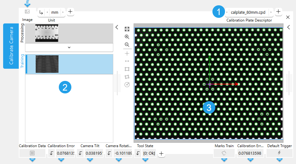
The Tool Board is split into the training area on the left of the and the graphics window on the right. The training area enables you to switch between the processing mode for choosing an image of a calibration plate and the training mode to train the calibration data. The graphics window will display the image of the currently active mode which is highlighted in blue. In addition to the parameters on the top left, the tool provides the parameter Calibration Plate Descriptor on the top right of the tool.
![]() Calibration Plate Descriptor
Calibration Plate Descriptor
![]() Training area
Training area
![]() Graphics window
Graphics window
How to Perform the Training
To perform a training, acquire an image of a calibration plate from a file or from a camera device. Insert the tool "Calibrate Camera". Connect the image to the "Image" parameter of the tool "Calibrate Camera" and select it as training image. The training starts automatically. For detailed information see How to Perform the Training.
Training Result Preview
To get a preview of the training results while the processing mode is active, you can set the parameter "Camera Setup Mode" to 1.
Camera Setup
If a camera setup is required, add the parameter "Camera Setup Mode" and set it to 1 to perform a calibration with every execution cycle of the MERLIC application. When the camera setup is finished, use the image as training image and set the parameter "Camera Setup Mode" to "0". This also saves run time. While the parameter "Camera Setup Mode" is set to 1 the training will also start automatically every time a parameter is changed.
Selecting the Training Image
The image on top of the left side in the Tool Board shows the image that is currently loaded, the image below shows the training image.
When the tool is inserted, the current processing image is automatically used as training image and the training is executed. You may also change the training image with the following steps:
- Run the application in single steps until the desired image is displayed in the graphics window and thus in the "Processing" area.
- Click on the
 button in the training area on the left to replace the current training image with the image from the "Processing" area. The training mode is automatically activated and the new training image is displayed in the graphics window.
Calibration Results
As soon as a training image is loaded, MERLIC shows which calibration marks are detected and provides calibration results if the calibration was successful with the default parameter settings. If "Camera Setup Mode" is set to "0" the tool results are always based on the last successful training.
After calibration, the world coordinate system has its center, i.e., position [0,0], on "Calibration Origin". It is a right-handed system, which means that a counterclockwise 90 degree rotation leads from the x-axis to the y-axis.
The calibration data can then be used in subsequent tools, i.e., to rectify the image with Rectify Image. Furthermore, this tool enables you to use a region of interest (ROI) to define a known length in an image and therefore specify the pixel size at a certain distance to the camera. This tool only calibrates in one measurement plane. By using an ROI you can define a reference length for objects that are parallel to the calibration plate but on a different level.
Calibration Plate
You need a calibration plate to calibrate your camera. You can obtain calibration plates in various sizes and materials from our sales partner in your region. Transparent calibration plates are available for applications requiring back light illumination. It is also possible to obtain personalized descriptor files for non standard calibration plates additional to those that are stored in the sub directory "calib".
For test purposes only, you can print calibration plates in the sizes 20 mm, 40 mm, 80 mm and 160 mm from the document "test_calibration_plates.pdf" that is provided in the "calib" directory of your MERLIC installation, for example, in "%PROGRAMFILES%\MVTec\MERLIC-26.03\calib\".
The calibration plates for printing are not accurate and cannot replace a real calibration plate. If you print the plates for testing purposes, make sure that your printer is set to print "actual size" or "100%" and does not scale or fit the document.
Rules for Good Calibration Results:
- Use a calibration plate that is big enough to fill a large part of the image.
- The minimum diameter of the circular marks should be 20 px.
- The white parts of the calibration plate should have a gray value of at least 100.
- The contrast between the foreground and the background of the calibration plate, i.e., its bright and dark parts, respectively, should be better than 100 gray values.
- Use an illumination where the calibration plate is represented with homogeneous gray values.
- The images must not be overexposed, which means that they should not have a peak at 255 in the histogram.
Parameters
Basic Parameters
Image:
This parameter represents the image used for calibrating the camera when the parameter "Camera Setup Mode" is set to 1. Images connected to this parameter can be set as training images.
If a color image is used as input image for this tool, only the first channel, i.e., the red channel, is used for the processing.
Unit:
Use this parameter to convert the unit of the "Calibration Data" from the calibration plate ("mm" by default) to a unit of your choice for the tool results. You can change its value at the corresponding connector. The results may vary slightly depending on the chosen unit. If a "Reference ROI" or a ROI with a given "Distance in World" was inserted, "Unit" is ignored.
|
Value |
Description |
|---|---|
|
nm |
The calibration information is specified in nm. |
|
μm |
The calibration information is specified in μm. |
|
mm |
The calibration information is specified in mm. |
|
cm |
The calibration information is specified in cm. |
|
m |
The calibration information is specified in m. |
|
point |
The calibration information is specified in point. |
|
pica |
The calibration information is specified in pica. |
|
inch |
The calibration information is specified in inch. |
|
foot |
The calibration information is specified in foot. |
|
yard |
The calibration information is specified in yard. |
Additional Parameters
Reference ROI:
This parameter contains the graphical representation of the reference distance, i.e., a distance of a known length that can be used to define a scale for a specific unit and the corresponding pixel size. It is represented as an ROI.
By default no "Reference ROI" is defined. If you want to use a "Reference ROI" for the calibration, you either have to connect the parameter to an appropriate ROI result of a previous tool to make sure that a "Reference ROI" is transmitted to this tool or you have to draw a new "Reference ROI" into the image using the available ROI buttons. Once a "Reference ROI" has been defined, it is necessary to enter the known length at the parameter "Distance in World".
This tool only supports the use of a single ROI. If the "Reference ROI" contains multiple ROIs, only the last created ROI will be used for the processing. If the "Reference ROI" is represented by a circular ROI, the diameter of the circle is used as reference distance. If a (paraxial) rectangle is used as "Reference ROI", the major length along its orientation is used as reference distance.
This is useful if you want to measure items that are not on the same plane as the calibration plate.
Distance in World:
This parameter defines the actual real life distance that corresponds to a specified known reference distance represented by the "Reference ROI". The "Reference ROI" defines a custom unit that will be used for subsequent measurements.
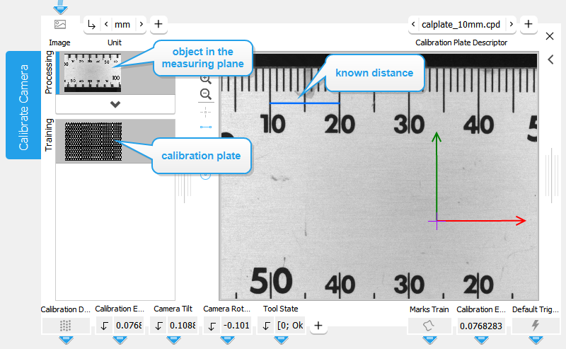
If the application object is positioned at a different distance to the camera, the pixel size can be determined as well as the distortion. After the successful calibration, acquire an image of an object in the measurement plane of the application. Use a segment ROI to mark a known distance and enter the values at the parameter connectors "Distance in World". Setting "Unit" is optional because MERLIC internally uses pixels for the computation. You should set it to an appropriate value anyway, e.g., "m", if you expect metric results from the measurement.
Camera Setup Mode:
This parameter defines the mode of the camera setup. If the "Camera Setup Mode" is turned on (1), the camera is calibrated with every execution cycle of MERLIC. This may be useful in applications with live images to set up the camera. You also get a preview of the training results while in the processing mode. If it is turned off, the calibration is only performed once to save run time. The parameter is set to 0 by default.
Training Parameters
Basic Training Parameters
Calibration Plate Descriptor:
This training parameter contains the descriptor file of the calibration plate used for the training. The calibration plate is an object whose shape is known precisely. It contains one to five finder patterns which consist of a special mark hexagon, i.e., a mark and its six neighbors, where either four or six marks contain a hole. Each of these finder patterns is unique such that it can be used to determine the orientation of the calibration plate and the position of the finder pattern on the calibration plate. At least one of these finder patterns must be completely visible for the training of the "Calibration Data".
Results
Basic Results
Calibration Data:
This result contains the determined calibration data needed for the correction of possible lens distortions and the position of the camera with respect to the image plane.
Calibration Error:
This result represents the average back projection error of the calibration. It is represented in pixel and gives general information whether the optimization was successful. It is generated from the training image if you set "Camera Setup Mode" to 1. Otherwise it is generated from the processing image.
A "Calibration Error" in the order of 0.1 px is an indication that the optimization fits the observation data well. If the "Calibration Error" strongly differs from 0.1 px, the calibration did not perform well.
Camera Tilt:
This result returns the tilt angle of the camera in degrees, i.e., the angle between the camera and the calibration plate. The tilt is returned as a real number in the value range from 0° to 90°. A "Camera Tilt" of 0° means that the camera is perpendicular to the calibration plate. If the "Camera Tilt" is 90°, the camera lies parallel to the calibration plate. This information can be used to adjust the camera during setup.
Camera Rotation:
This result returns the rotation of the camera in degrees, i.e., the rotation with respect to the alignment of the calibration plate. The rotation is returned as a real number in the value range from −180° to 180°. The following table describes how the calibration plate can be rotated.
|
Camera rotation |
Example image |
Description |
|---|---|---|
|
Camera Rotation = 0 |
|
The calibration plate is not rotated:
|
|
Camera Rotation > 0 |
|
The calibration plate is rotated clockwise:
The example image shows a calibration plate that is rotated clockwise by 40°. The determined "X Axis" (red) and "Y Axis" (green) visualize the orientation of the calibration plate. The resulting "Camera Rotation" in the example is "40". |
|
Camera Rotation < 0 |
|
The calibration plate is rotated counterclockwise:
The example image shows a calibration plate that is rotated counterclockwise by 40°. The determined "X Axis" (red) and "Y Axis" (green) visualize the orientation of the calibration plate. The resulting "Camera Rotation" is "−40". |


In case the "Camera Rotation" is 180° or −180°, it might happen that the result jumps between −180° and 180°. The information of the "Camera Rotation" can be used to adjust the camera during setup.
Tool State:
"Tool State" returns information about the state of the tool and thus can be used for error handling. For more information, see Tool State Result
Additional Results
Calibration Origin:
This result returns the origin of the used calibration plate, i.e., the center of the coordinate system. The result is returned as a point ROI.
Maximum Local Error:
This result returns the maximum error between each mark and its back projection. Therefore the distance to the corresponding back projected mark is determined. The maximum deviation is then returned in pixels as a real value.
Maximum Global Error:
This result returns the maximum global error. Therefore the distance between the mark in the upper left and the mark in the lower right corner is determined and compared to the corresponding distance in the back projection. The maximum deviation is then returned in pixels as a real value.
Marks:
This result contains the contours of the calibration marks that were extracted from the processing image. "Marks" delivers different results depending on the setting for the parameter "Camera Setup Mode".
If "Camera Setup Mode" is set to 1, "Marks" returns the extracted calibration marks from the processing image. This may be useful to compare the calibration data. In case the processing image shows no calibration plate, no calibration marks can be extracted and therefore "Marks" is empty.
If "Camera Setup Mode" is set to "0", "Marks" is empty because no calibration is performed at the processing image.
X Axis:
This result represents the determined x-axis. The result is returned as a contour and visualized in red.
Y Axis:
This result represents the determined y-axis. The result is returned as a contour and visualized in green.
Processing Time:
This result returns the duration of the most recent execution of the tool in milliseconds. The result is provided as additional result. Therefore, it is hidden by default but it can be displayed via the ![]() button beside the tool results. For more information see the section Processing Time in the tool reference overview.
button beside the tool results. For more information see the section Processing Time in the tool reference overview.
Training Results
Basic Training Results
Marks Train:
This result returns the contours of the found calibration marks.
Calibration Error Train:
This result returns the calibration error in pixels.
Application Examples
This tool is used in the following MERLIC Vision App examples:
- calibrate_for_ruler_changed_distance.mvapp
- calibrate_for_ruler_distorted.mvapp
- calibrate_for_ruler_simple.mvapp

