Transform Regions
Use this tool to transform regions using different methods.
The tool requires that the regions are available and delivered from a previous tool. Therefore, the parameter "Regions" must be connected with an appropriate result of a previous tool.
Parameters
Basic Parameters
Image:
Use this parameter to set an image as background. This should usually be the image, the processed features e.g., contours or ROIs are based on. If no image is connected, the background will be black.
Regions:
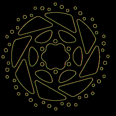
This parameter represents the input regions. The regions must be taken over from a previous tool. Therefore, you have to connect the parameter with the respective result of a previous tool. The connected region is then used as input for the transformation. The margin of the regions is highlighted in the defined color for 'region input', e.g., red by default. This makes it easier to distinguish the input regions from the transformed regions.
Method:
This parameter defines the method used to transform the regions. As a default, "filled" is selected as "Method". You can select a different method from the combo box of the corresponding parameter.
|
Value |
Description |
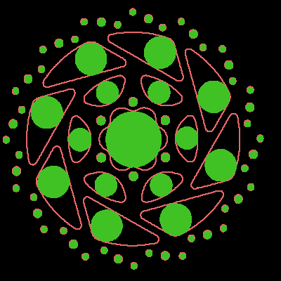
Original Region |
Transformed Region |
|---|---|---|---|
|
filled |
Use this method to fill regions. The number of regions remains unchanged. |
|
|
|
convex hull |
Use this method to calculate a convex hull around each region. |
|
|
|
equivalent ellipse |
Use this method to calculate an ellipse sharing the same moments and areas as each region. |
|
|
|
outer circle |
Use this method to calculate the smallest circle that fits around each region. Due to the computation the original region might protrude beyond the returned circular region by at most 1 pixel. |
|
|
|
inner circle |
Use this method to calculate the largest circle that fits within each region. |
|
|
|
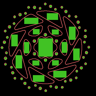
paraxial rectangle |
Use this method to calculate the smallest paraxial rectangle that fits around each region in the image. |
|
|
|
rectangle |
Use this method to calculate the smallest rectangle that fits around each region in the image. |
|
|
|
inner paraxial rectangle |
Use this method to calculate the largest paraxial rectangle that fits within a each region. |
|
|
|
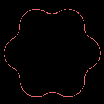
inner center |
Use this method to get the point on the skeleton with the smallest distance to the center of gravity of the input region. |
|
|
|
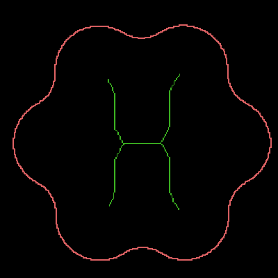
skeleton |
Use this method to calculate the skeleton of each region, i.e., the medial axis of the input regions. The skeleton is constructed in a way that each point on it can be seen as the center point of a circle with the largest radius possible while still being completely contained in the region. |
|
|
|
complement |
Use this method to get the complement of the region. The computation uses the complement of "union" intersected with the domain of the original image. |
|
|
|
union |
Use this method to join separate regions into one region that consists of all input regions. This union is not visualized. This method is the inverse of "separate". |
|
|
|
separate |
Use this method to split one region that consists of separate elements into regions for each element. This separation is not visualized. This method is the inverse of "union". |
|
|
|
border |
Use this method to get the borders of each region. The contour computation is done using morphological operations. The resulting output regions consist only of the minimal border of the input regions. The contour lies within the original region. |
|
|


Results
Basic Results
Transformed Regions:
The result is a region that has been transformed with a selected method.
Tool State:
"Tool State" returns information about the state of the tool and thus can be used for error handling. For more information, see Tool State Result
Additional Results
Processing Time:
This result returns the duration of the most recent execution of the tool in milliseconds. The result is provided as additional result. Therefore, it is hidden by default but it can be displayed via the ![]() button beside the tool results. For more information see the section Processing Time in the tool reference overview.
button beside the tool results. For more information see the section Processing Time in the tool reference overview.
Application Examples
This tool is used in the following MERLIC Vision App examples:
- classify_and_inspect_wood.mvapp
- count_defect_clusters.mvapp

