Read Aztec Code
Use this tool to detect and read one or more codes of the type Aztec in an image. If the tool is added, the current processing image is automatically scanned and by default the first Aztec code on it is read.
Training
This tool is used with a training mode. easyTouch and easyTouch+ can be used to estimate values in the current image in the processing mode. This may be useful to find out, whether the codes in the image can be read at all. The training mode should then be used to determine the best parameter settings with a series of images.
- Run the application step by step via the "Run Once" button or via the shortcut F6 until an image is shown that you want to use as training image.
- Add the current image to the set of training images by clicking on the
 button or by using the shortcut F3. The tool automatically highlights the possible contours of the codes in the images.
 - If necessary, draw an ROI over the code.
- To add further training images, repeat the previous steps again.
- Click on the "Apply training data" button to perform the training. The parameters for the set of training images are automatically determined. In addition, the tool automatically switches to the processing mode and shows the detected codes in the current image.
Check the training
- Click on the processing image to switch to the processing mode.
- Run MERLIC with a series of images to check whether the codes are detected and read.
- To check the decoded data of a specific code, move the mouse pointer over the code in the image. The decoded data will be instantly shown in a tooltip. Alternatively, you can also check the decoded data in the respective tool result.
Tool Structure
The Tool Board is split into the training area on the left of the and the graphics window on the right.
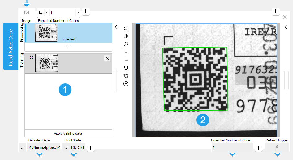
![]() Training area
Training area
![]() Graphics window
Graphics window
The first image on the left side of the Tool Board shows the image that is currently loaded. At this stage MERLIC already provides a preview of all found codes and already provides results if the reading was successful with the default parameter settings.
You have to select the training image by clicking on the ![]() button to transfer the image shown in "Processing" to the "Training" area. You can also add an additional image. To do so, run the program in single steps until the image you want to use as training image is shown in "Processing" and press the
button to transfer the image shown in "Processing" to the "Training" area. You can also add an additional image. To do so, run the program in single steps until the image you want to use as training image is shown in "Processing" and press the ![]() button. In any case, press the button "Apply training data" to adapt the parameters to the training image.
button. In any case, press the button "Apply training data" to adapt the parameters to the training image.
The parameters can then be tested with further images within the same tool. See the topic Working with the Training Mode to learn more about how to work with tools that require a training.
Parameters
Basic Parameters
Image:
This parameter represents the image in which the Aztec code should be read.
If a color image is used as input image for this tool, only the first channel, i.e., the red channel, is used for the processing.
Expected Number of Codes:
This parameter defines the expected number of codes that are present in the image. As a default, this value is set to 1. If less codes are found than the expected number, the code reading fails.
Due to the image processing that is in use, it is possible that the tool will find more than the minimum expected number of codes. In this case use an ROI to restrict the area of the data code detection.
Additional Parameters
Processing Region:
This parameter defines the region for processing. Image parts outside of the union of the ROI and "Processing Region" are not processed. In addition, if either of them is empty, the image part inside of the other one is processed. In case both of them are empty, the whole image is processed.
By default, "Processing Region" is defined as empty region. To specify a "Processing Region", you have to connect the parameter to an appropriate region result of a previous tool to make sure that a region is transmitted to this tool.
If easyTouch is used to determine the parameters values, the whole image is used for the search.
ROI:
The parameter "ROI" defines the region of interest (ROI) for the code detection. Image parts outside of the union of the "ROI" and the "Processed Region" are not processed.In addition, if either of them is empty, the image part inside of the other one is processed. In case both of them are empty, the whole image is processed. However, if easyTouch is used to determine the parameter values, the whole image is used for the processing.
By default the ROI is defined as an empty ROI. If you want to use a non-empty ROI for the processing, you either have to connect the parameter to an appropriate ROI result of a previous tool or you have to draw new ROIs into the image using the available ROI buttons.
If easyTouch is used to determine the parameters values, the whole image is used for the search.
Alignment Data:
This parameter represents the alignment data that are used to align the ROI. By default no alignment data are connected and thus no effect is visible. If you want to use specific alignment data, you have to connect the parameter to an appropriate result of a previous tool such as Determine Alignment with Matching, Determine Alignment with Straight Border, Align Image, or Rotate Image.
Timeout:
By using this parameter, it is possible to interrupt the execution of the tool after a defined period in milliseconds. This is especially useful in cases where a maximum cycle time has to be ensured. The temporal accuracy of this interrupt is about 10 ms. The accuracy depends on several factors including the speed of your computer. The timeout is ignored in training mode. The default timeout is 0 ms.
|
Value |
Description |
|---|---|
|
0 |
As a default, no timeout is set. |
|
1 - 1000 |
This is the available value range for setting the timeout in milliseconds. |
Minimum Contrast:
This parameter represents the minimum gray value contrast between the foreground and the background of the symbol. The default setting is 30.
|
Value |
Description |
|---|---|
|
30 |
This is the default minimum contrast. The gray values of the foreground and background have to differ from another at least by a value of 30. |
|
1 - 255 |
This is the available value range for setting the minimum contrast. |
Finder Pattern Tolerance:
This parameter represents the tolerance of the search with respect to a defect or partially occluded finder pattern. Depending on this parameter, different algorithms are used during the symbol search. The default setting is "low".
|
Value |
Description |
|---|---|
|
low |
It is assumed that all rings of the finder pattern can be extracted; the finder pattern is not occluded and shows almost no disturbances. |
|
high |
It is assumed that at least one of the rings of the finder pattern can be extracted and that the finder pattern is at least partially occluded (not all rings are visible). As a consequence of using the different algorithm, the run time increases. |
|
any |
It is assumed that the finder pattern may or may not be occluded - therefore both algorithms are applied. |
Mirrored Code:
This parameter describes whether the symbol is or may be mirrored which is equivalent to swapping rows and columns of the symbol. The default setting is "no".
|
Value |
Description |
|---|---|
|
no |
The code does not appear mirrored. |
|
yes |
The code always appears mirrored. |
|
any |
The code may appear mirrored. |
Minimum Gap Width
This parameter defines the minimum gap width in direction of the symbol rows and columns. The default setting is "no".
|
Value |
Description |
|---|---|
|
no |
There is no minimum gap width. |
|
small |
The gap width is at least small. |
|
big |
The gap width is big. |
Maximum Gap Width
This parameter defines the maximum gap width in direction of the symbol rows and columns. The default setting is "small".
|
Value |
Description |
|---|---|
|
no |
There is no maximum gap width. |
|
small |
A small gap is allowed. |
|
big |
A big gap is allowed. |
Minimum Module Size:
This parameter specifies the minimum size of the modules in the image. It is defined in pixels and set to 6 px by default.
|
Value |
Description |
|---|---|
|
6 |
This is the default minimum module size. All symbols with a module size higher than 6 can potentially be read. |
|
1 - 100 |
This is the available value range for setting the minimum module size. |
Maximum Module Size:
This parameter specifies the maximum size of the symbol modules. It is defined in pixels and set to 20 px by default.
|
Value |
Description |
|---|---|
|
20 |
This is the default maximum module size. All symbols with a module size up to 20 pixels can potentially be read. |
|
2 - 100 |
This is the available value range for setting the maximum module size. |
Code Property:
The parameter determines if the symbol appears dark on a light background or light on a dark background. The default setting is "dark".
|
Value |
Description |
|---|---|
|
dark |
The symbol appears dark on a light background. |
|
light |
The symbol appears light on dark background. |
|
any |
The symbol may appear either dark on light background or light on dark background. |
Robust Against Small Modules:
This parameter defines the robustness of the decoding of data codes with very small module sizes. Setting the parameter "Robust Against Small Modules" to 1, which is high, increases the likelihood of being able to decode data codes with very small module sizes. Additionally, in that case the minimum module size should also be adapted accordingly. Setting "Robust Against Small Modules" to 1 can significantly increase the internal memory usage of the tool. Therefore the default setting is 0, which means low.
|
Value |
Description |
|---|---|
|
0 |
This is the default setting. Use this setting if only a low robustness against small modules is required. |
|
1 |
Use this setting if a high robustness against small modules is required. This setting increases the memory usage. |
Conform to Standard:
This parameter controls the behavior of the tool while reading symbols that do not fit the specified model restrictions on the size. The parameter is set to 0 by default.
|
Value |
Description |
|---|---|
|
0 |
The code is not conform to standard: All symbols are returned as a result, independent of their size and the size specified in the model. |
|
1 |
The code is conform to standard: All other symbols that are not conform to the standard's restrictions are rejected. |
Minimum Code Size:
This parameter defines the minimum size of the complete code in modules. The default setting is 11.
|
Value |
Description |
|---|---|
|
11 |
All codes with at least 11 modules can potentially be read. |
|
11 - 151 |
This is the available value range for setting the minimum code size. |
Maximum Code Size:
This parameter defines the maximum size of the complete code in modules. The default setting is 151.
|
Value |
Description |
|---|---|
|
151 |
All codes with up to 151 modules can potentially be read. |
|
11 - 151 |
This is the available value range for setting the maximum code size. |
Print Quality:
This parameter defines if the print quality is evaluated and based on which verification standard. The default setting is "none".
|
Value |
Description |
|---|---|
|
none |
The print quality evaluation is disabled. |
|
ISO/IEC 15415 |
The print quality is evaluated based on verification standard ISO/IEC 15415:2024. |
|
ISO/IEC 29158 |
The print quality is evaluated based on verification standard ISO/IEC 29158:2025. ISO/IEC 29158:2025 is an extension of the ISO/IEC 15415:2024 standard that specifically addresses print quality grading for "direct part marking" (DPM) symbols. |
Results
Basic Results
Decoded Data:
The result is a string with the decoded data. If more than one code is read, the result is returned in a tuple. The tuple entries are sorted with respect to their "row" and "column" values in which they appear in the image. Thus, if several lines are read, the decoded data of the first line are returned at first, then the data of the second line, etc. In case there are several codes within a line, they are returned from left to right until the next line is processed such like a text.
The decoded data of a specific code is also shown if you move the mouse pointer over the code in the image. This way, you can quickly check the codes directly in the image.
Tool State:
"Tool State" returns information about the state of the tool and thus can be used for error handling. For more information, see Tool State Result
Additional Results
Extracted Contour:
This result is the contour of the detected data code(s).
Print Quality Values:
This result returns the values that are evaluated for the print quality features of the selected verification standard. They are returned as a tuple and sorted according the order of the labels of the print quality features in the result "Print Quality Features". Thus, the first value in the tuple represents the print quality value of the first feature returned in the "Print Quality Features" result. The second value represents the second feature and so on. The maximum possible value is 4. For Print Quality Features where the print quality is too low, the value 0 is returned. If no verification standard is selected, that is, if "Print Quality" is set to "none" an empty tuple is returned for this result.
Print Quality Features:
This result returns the labels of the print quality features that are evaluated for the selected verification standard. The feature lists of the supported verification standards are predefined and do not change during the processing. They are returned in a tuple of strings. The tuple value returned for each feature corresponds to an individual value in the result "Print Quality Values" with the same index. If no verification standard is selected, that is, if "Print Quality" is set to "none", an empty list is returned for this result.
Processing Time:
This result returns the duration of the most recent execution of the tool in milliseconds. The result is provided as additional result. Therefore, it is hidden by default but it can be displayed via the ![]() button beside the tool results. For more information see the section Processing Time in the tool reference overview.
button beside the tool results. For more information see the section Processing Time in the tool reference overview.
Training Results
Basic Training Results
Expected Number of Codes Out:
This result returns the value used for the parameter Expected Number of Codes. It defines the expected number of codes that are present in the image.
Additional Training Results
Minimum Contrast Out:
This result returns the value used for the following parameter: Minimum Contrast. It represents the minimum gray value contrast between the foreground and the background of the symbol.
Finder Pattern Tolerance Out:
This result returns the value used for the following parameter: Finder Pattern Tolerance. It represents the tolerance of the search with respect to a defect or partially occluded finder pattern.
Mirrored Code Out:
This result returns the value used for the following parameter: Mirrored Code. It describes whether the symbol is or may be mirrored.
Maximum Gap Width Out:
This result returns the value used for the following parameter: Maximum Gap Width.
Minimum Gap Width Out:
This result returns the value used for the following parameter: Minimum Gap Width.
Maximum Module Size Out:
This result returns the value used for the following parameter: Maximum Module Size. It represents the maximum size of the symbol modules in pixels.
Minimum Module Size Out:
This result returns the value used for the following parameter: Minimum Module Size. It represents the minimum size of the symbol modules in pixels.
Code Property Out:
This result returns the value used for the following parameter: Code Property. It determines if the symbol appears dark on a light background or light on a dark background
Robust Against Small Modules Out:
This result returns the value used for the following parameter: Robust Against Small Modules. It defines the robustness of the decoding of data codes with very small module sizes.
Conform to Standard Out:
This result returns the value used for the following parameter: Conform to Standard. It controls the behavior of the tool while reading symbols that do not fit the model restrictions on their size.
Maximum Code Size Out:
This result returns the value used for the following parameter: Maximum Code Size. It defines the maximum size of the complete code in modules.
Minimum Code Size Out:
This result returns the value used for the following parameter: Minimum Code Size. It defines the minimum size of the complete code in modules.

