Read Bar Code
Use this tool to detect and read one or more bar codes of different types in an image. If the tool is added, the current processing image is automatically scanned and by default all bar codes on it are read.
Training
This tool is used with a training mode. easyTouch and easyTouch+ can be used to estimate values in the current image in the processing mode. This may be useful to find out, whether the codes in the image can be read at all. The training mode should then be used to determine the best parameter settings with a series of images.
- Run the application step by step via the "Run Once" button or via the shortcut F6 until an image is shown that you want to use as training image.
- Add the current image to the set of training images by clicking on the
 button or by using the shortcut F3. The tool automatically highlights the possible contours of the codes in the images.
 - If necessary, draw an ROI over the code.
- To add further training images, repeat the previous steps again.
- Click on the "Apply training data" button to perform the training. The parameters for the set of training images are automatically determined. In addition, the tool automatically switches to the processing mode and shows the detected codes in the current image.
If the training mode is active, the parameter "Code Type" is not determined automatically. It is determined automatically only in the processing mode when using easyTouch.
When applying the training, only a specific set of parameters is changed:
- Minimum Element Width
- Maximum Element Width
- Minimum Relative Edge Amplitude
- Minimum Absolute Edge Amplitude
- Orientation
- Orientation Tolerance
In contrast, if the processing mode is active, only the following parameters are changed automatically when using easyTouch:
- Code Type
- Minimum Bar Code Width
- Maximum Element Width
- Minimum Absolute Edge Amplitude
The selected values of all other parameters will therefore influence the result of the training.
Check the training
- Click on the processing image to switch to the processing mode.
- Run MERLIC with a series of images to check whether the codes are detected and read.
- To check the decoded data of a specific code, move the mouse pointer over the code in the image. The decoded data will be instantly shown in a tooltip. Alternatively, you can also check the decoded data in the respective tool result.
Tool Structure
The Tool Board is split into the training area on the left of the and the graphics window on the right.
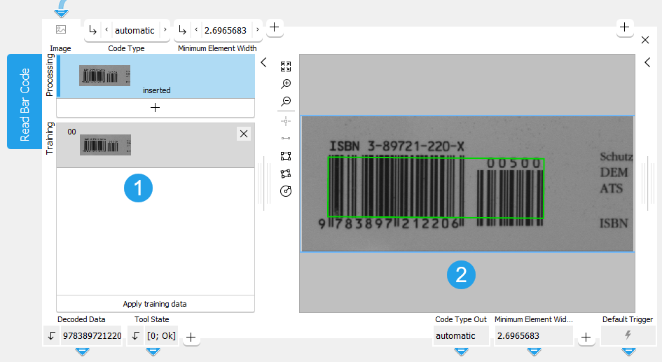
![]() Training area
Training area
![]() Graphics window
Graphics window
The first image on the left side of the Tool Board shows the image that is currently loaded. At this stage MERLIC already provides a preview of all found codes and already provides results if the reading was successful with the default parameter settings.
You have to select the training image by clicking on the ![]() button to transfer the image shown in "Processing" to the "Training" area. You can also add an additional image. To do so, run the program in single steps until the image you want to use as training image is shown in "Processing" and press the
button to transfer the image shown in "Processing" to the "Training" area. You can also add an additional image. To do so, run the program in single steps until the image you want to use as training image is shown in "Processing" and press the ![]() button. In any case, press the button "Apply training data" to adapt the parameters to the training image.
button. In any case, press the button "Apply training data" to adapt the parameters to the training image.
The parameters can then be tested with further images within the same tool. See the topic Working with the Training Mode to learn more about how to work with tools that require a training.
Parameters
Depending on the selected code type at the parameter "Code Type", some connectors are grayed out. This means that they are not applicable for the currently selected code type and thus have no effect.
Basic Parameters
Image:
This parameter represents the image in which the bar code should be read.
If a color image is used as input image for this tool, only the first channel, i.e., the red channel, is used for the processing.
Code Type:
Select the type of the codes. As a default "automatic" is selected. Click on a code that should be read to set the parameter to this code type. Setting the code type to a specific type (if possible) may lead to a better training result.
|
Value |
Description |
|---|---|
|
automatic |
All code types are detected and read. |
|
2/5 Industrial |
Codes of the type "2/5 Industrial" are detected and read. |
|
2/5 Interleaved |
Codes of the type "2/5 Interleaved" are detected and read. |
|
|
Codes of the type "" are detected and read. |
|
Code 39 |
Codes of the type "Code 39" are detected and read. |
|
Code 93 |
Codes of the type "Code 93" are detected and read. |
|
Code 128 |
Codes of the type "Code 128" are detected and read. |
|
EAN-13 |
Codes of the type "EAN-13" are detected and read. |
|
EAN-13 Add-On 2 |
Codes of the type "EAN-13 Add-On 2" are detected and read. |
|
EAN-13 Add-On 5 |
Codes of the type "EAN-13 Add-On 5" are detected and read. |
|
EAN-8 |
Codes of the type "EAN-8" are detected and read. |
|
EAN-8 Add-On 2 |
Codes of the type "EAN-8 Add-On 2" are detected and read. |
|
EAN-8 Add-On 5 |
Codes of the type "EAN-8 Add-On 5" are detected and read. |
|
UPC-A |
Codes of the type "UPC-A" are detected and read. |
|
UPC-A Add-On 2 |
Codes of the type "UPC-A Add-On 2" are detected and read. |
|
UPC-A Add-On 5 |
Codes of the type "UPC-A Add-On 5" are detected and read. |
|
UPC-E |
Codes of the type "UPC-E" are detected and read. |
|
UPC-E Add-On 2 |
Codes of the type "UPC-E Add-On 2" are detected and read. |
|
UPC-E Add-On 5 |
Codes of the type "UPC-E Add-On 5" are detected and read. |
|
MSI |
Codes of the type "MSI" are detected and read. |
|
PharmaCode |
Codes of the type "PharmaCode" are detected and read. "PharmaCode" can be read from left to right or from right to left which leads to different results. Without training, only using easyTouch, "Decoded Data" will contain both results. The training mode establishes the reading orientation from left to right leading to a single result. |
|
GS1 DataBar Omnidir |
Codes of the type "GS1 DataBar Omnidir" are detected and read. |
|
GS1 DataBar Truncated |
Codes of the type "GS1 DataBar Truncated" are detected and read. |
|
GS1 DataBar Stacked |
Codes of the type "GS1 DataBar Stacked" are detected and read. |
|
GS1 DataBar Stacked Omnidir |
Codes of the type "GS1 DataBar Stacked Omnidir" are detected and read. |
|
GS1 DataBar Limited |
Codes of the type "GS1 DataBar Limited" are detected and read. |
|
GS1 DataBar Expanded |
Codes of the type "GS1 DataBar Expanded" are detected and read. |
|
GS1 DataBar Expanded Stacked |
Codes of the type "GS1 DataBar Expanded Stacked" are detected and read. |
|
GS1-128 |
Codes of the type "GS1-128" are detected and read. |
Minimum Element Width:
This parameter defines the minimal size of bar code elements, i.e., the minimal width of bars and spaces. It is defined in pixels and set to 2 px by default. For low resolution bar codes, the value should be reduced to 1.5 px, and in some cases even as low as 1.2 px. In case of huge bar codes, the value should be increased, which results in a shorter execution time and fewer candidates.
If the training does not return satisfying results, it may help to adapt the value for "Minimum Element Width" manually after the training.
|
Value |
Description |
|---|---|
|
2 |
This is the default minimum element width. All symbols with a minimum element width of at least 2 px can potentially be read. |
|
1.2 - 10 |
This is the available value range for setting the minimum element width. |
Additional Parameters
Processing Region:
This parameter defines the region for processing. Image parts outside of the union of the ROI and "Processing Region" are not processed. In addition, if either of them is empty, the image part inside of the other one is processed. In case both of them are empty, the whole image is processed.
By default, "Processing Region" is defined as empty region. To specify a "Processing Region", you have to connect the parameter to an appropriate region result of a previous tool to make sure that a region is transmitted to this tool.
If easyTouch is used to determine the parameters values, the whole image is used for the search.
ROI:
The parameter "ROI" defines the region of interest (ROI) for the code detection. Image parts outside of the union of the "ROI" and the "Processed Region" are not processed.In addition, if either of them is empty, the image part inside of the other one is processed. In case both of them are empty, the whole image is processed. However, if easyTouch is used to determine the parameter values, the whole image is used for the processing.
By default the ROI is defined as an empty ROI. If you want to use a non-empty ROI for the processing, you either have to connect the parameter to an appropriate ROI result of a previous tool or you have to draw new ROIs into the image using the available ROI buttons.
If easyTouch is used to determine the parameters values, the whole image is used for the search.
Alignment Data:
This parameter represents the alignment data that are used to align the ROI. By default no alignment data are connected and thus no effect is visible. If you want to use specific alignment data, you have to connect the parameter to an appropriate result of a previous tool such as Determine Alignment with Matching, Determine Alignment with Straight Border, Align Image, or Rotate Image.
Expected Number of Codes:
This parameter defines the expected maximum number of codes present in the image. After this number is reached, no more execution time is spent searching for further candidate regions. As a default, this parameter is set to (0). This means that all bar code candidates are returned. However, if codes are difficult to read, they may not be found with this setting. In general, if the number set for this parameter is lower than the actual number of codes in the image, those codes may not be found if they are difficult to read since returning these codes would lead to a higher execution time.
This parameter can be used to reduce the execution time if not all codes in the image are required. In this case, it is useful to specify the expected number. If a number is specified, MERLIC may still return more codes than the selected number, but only if it does not increase the execution time.
Timeout:
By using this parameter, it is possible to interrupt the execution of the tool after a defined period in milliseconds. This is especially useful in cases where a maximum cycle time has to be ensured. The temporal accuracy of this interrupt is about 10 ms. The accuracy depends on several factors including the speed of your computer. The timeout is ignored in training mode. The default timeout is 0 ms.
|
Value |
Description |
|---|---|
|
0 |
As a default, no timeout is set. |
|
1 - 1000 |
Available value range for setting the timeout in milliseconds. |
Minimum Bar Code Height:
This parameter defines the minimal bar code height. It is defined in pixels and set to 0 px, meaning that the bar code reader automatically derives a reasonable height from the other parameters. Just for very flat and very high bar codes a manual adjustment of this parameter may be necessary. In the case of a bar code with a height of less than 16 px the respective height should be set by the user. Note, that the minimum value is 8 px. If the bar code is very high, i.e., 70 px and more, manually adjusting to the respective height can lead to a speed-up of the subsequent finding and reading operation.
|
Value |
Description |
|---|---|
|
0 |
This is the default value for minimum bar code height. All symbols can potentially be read. |
|
0 - 64 |
This is the available value range for setting the minimum bar code height in pixels. |
Minimum Bar Code Width:
This parameter defines the minimal bar code width. It is defined in pixels and set to 0 px by default. The width of a bar code depends on many factors:
- Resolution of the camera
- Distance between camera and bar code
- Bar code type
- Number of encoded characters
If these properties are constant throughout the application, this parameter should be set in order to increase both speed and robustness. The default value of 0 px means that the reader estimates a minimal bar code width based on symbology specifications and the parameter "Minimum Element Width".
|
Value |
Description |
|---|---|
|
0 |
Default value for minimum bar code width; all symbols can potentially be read. |
|
0 - 100 |
Available value range for setting the minimum bar code width in pixels. |
Check Character:
This parameter defines how to interpret bar codes with an optional check character. The default setting is "absent", but bar code types with a mandatory check character are always treated as if this parameter were set to "present".
Bar code types with an optional check character:
- Code 39
- 2/5 Industrial
- 2/5 Interleaved
|
Value |
Description |
|---|---|
|
absent |
The tool assumes that no check character is present. In this case, no check is performed and all characters are returned as data. |
|
preserved |
This value allows to verify the bar code while still keeping the check character in the data. |
|
present |
If this value is selected, a check character is expected and used to verify the correctness of the bar code. No bar code result is returned if the check sum does not match, and the check character itself is stripped from the data. |
Composite Code:
Most of the GS1 conform bar codes can have an additional 2D GS1 Composite code component appended. If the searched bar code symbol has no attached composite component, just the result of the bar code itself is returned. Currently, composite codes are supported only for bar codes of the GS1 DataBar family. The default setting is "absent".
|
Value |
Description |
|---|---|
|
ignore |
The composite code component is ignored. |
|
CC-A/B |
If this value is selected, the composite component will be found and decoded. |
Maximum Element Width:
This parameter represents the maximal size of bar code elements, i.e., the maximal width of bars and spaces. It is defined in pixels and set to 8 px by default. It should be adequately low to prohibit that two neighboring bar codes are fused into a single one. On the other hand the value should be sufficiently high in order to find the complete bar code region.
|
Value |
Description |
|---|---|
|
8 |
Default maximum element width; all symbols with an element width of up to 8 px can potentially be read. |
|
4 - 60 |
Available value range for setting the maximum element width. |
Element Width Tolerant:
In some bar code images, the smallest element size may vary across a given bar code object. These deformations might be caused by perspective projection or by deformations of the surface on which the bar code is printed (e.g., barrel distortion on a bottle). By default, this parameter is set to 0, thus the bar code reader cannot handle such distortions.
In some situations it is not possible to rectify the bar code image.
The parameter "Element Width Tolerant" applies to the following bar code types only:
- GS1 DataBar Limited
- GS1 DataBar Expanded
- GS1 DataBar Expanded Stacked
- GS1-128
- Code 128
Any other bar code type is unaffected by this parameter.
|
Value |
Description |
|---|---|
|
0 |
The tool will not handle distortions. |
|
1 |
The tool tries to compensate for distortions. |
Minimum Relative Edge Amplitude:
This parameter defines a threshold, which is a relative value with respect to the dynamic range of the scanline pixels. The bar-space-sequence of a bar code is determined with a scanline measuring the position of the edges. Finding these edges requires the mentioned threshold. In the case of disturbances in the bar code region or a high noise level, the value of "Minimum Relative Edge Amplitude" should be increased.
|
Value |
Description |
|---|---|
|
0.05 |
This is the default value for the minimum relative edge amplitude. All symbols with a relative edge amplitude of at least 0.05 can potentially be read. |
|
0.01 - 0.2 |
This is the available value range for setting the minimum relative edge amplitude. |
Minimum Absolute Edge Amplitude:
If a scanline is laid in an image region with no or just very small gray value dynamic range (e.g., in a white region with all gray values near 255), the edge detection threshold based on "Minimum Relative Edge Amplitude" would be computed unreasonably small. This leads typically to the detection of a big amount of false edges. "Minimum Absolute Edge Amplitude" is used to prevent such misdetections. If the threshold value based on "Minimum Relative Edge Amplitude" gets smaller than the value of "Minimum Absolute Edge Amplitude", the latter is used as threshold instead. By default, "Minimum Absolute Edge Amplitude" is set to 5. A greater value might be more appropriate for images with high noise levels. On the other hand, in noise-free images with very weak contrast, this parameter might disturb the detection of real edges, so it might be necessary to reduce it or even completely disable it by setting it to 0.
|
Value |
Description |
|---|---|
|
5 |
This is the default value for the minimum absolute edge amplitude. All symbols with an absolute edge amplitude of at least 5 can potentially be read. |
|
0 - 10 |
This is the available value range for setting the minimum absolute edge amplitude. |
Minimum Identical Scanlines:
This parameter represents the minimal number of successfully decoded scanlines, which return identical data. These scanlines are relevant to decide whether a bar code symbol can be accepted. If this parameter is set to 1, a bar code is considered decoded with the first scanline, which was successfully decoded. In case of stacked codes, it must be a successful scanline per symbol row.
Increasing this parameter to 2, which is the default, or more, is particularly useful, since it reduces the risk of incorrectly detected bar codes. This can typically happen if a scanline extracted erroneous or false edges from a low quality image or in a very noisy image fragment. Setting this parameter is also useful if a specific bar code type is searched for in an image containing symbols from other bar code symbologies as well.
|
Value |
Description |
|---|---|
|
2 |
This is the default value for the minimum number of identical scanlines. All symbols with at least two identical scanlines can potentially be read. |
|
1 - 8 |
This is the available value range for setting the minimum identical scanlines. |
Orientation:
This parameter represents the expected bar code orientation. It is defined in degrees and set to 0° by default. A potential bar code contains bars with similar orientation. The "Orientation" and "Orientation Tolerance" parameters are used to specify the range. This tool processes a bar code only when the average orientation of its bars lies in this range. If the bar codes are expected to appear only in certain orientations in the processed images, one can reduce the orientation range adequately. This enables an early identification of false candidates and hence shorter execution times. This adjustment can be used for images with a lot of texture, which includes fragments likely to result in false bar code candidates.
|
Value |
Description |
|---|---|
|
0 |
This is the default value for the bar code orientation in degrees. |
|
−90 to 90 |
This is the available value range for setting the bar code orientation. |
Orientation Tolerance:
This parameter represents the orientation tolerance for the bars. It is defined in degrees and set to 90° by default. Please refer to the explanation of the "Orientation" parameter for further information. As explained there, relevant orientation values must be in the range of −90° to 90°, which means that with an "Orientation Tolerance" of 90° the whole range is present. Therefore, valid values for "Orientation Tolerance" are only in the range of 0° to 90°. The default value 90° means that no restriction to the bar code candidates is applied.
|
Value |
Description |
|---|---|
|
90 |
This is the default value for the bar code orientation tolerance in degrees (no restrictions). |
|
0 - 90 |
This is the available value range for setting the bar code orientation tolerance. |
Quiet Zone:
This parameter enforces the verification of the quiet zones of a bar code symbol. When enabled, scanlines are rejected when unexpected bars are detected within the quiet zones both left or right of a detected bar code sequence. With "Quiet Zone" set to "undisturbed" the quiet zones must be at least as wide as specified by the corresponding bar code standard. The default setting is "noisy".
The following values apply (in X units, where X stands for 'module width' and corresponds to the smallest width of a bar in the sequence):
|
Bar code type |
Left quiet zone |
Right quiet zone |
|---|---|---|
|
2/5 Industrial |
10 |
10 |
|
2/5 Interleaved |
10 |
10 |
|
|
10 |
10 |
|
Code 39 |
10 |
10 |
|
Code 93 |
10 |
10 |
|
Code 128 |
10 |
10 |
|
EAN-13 |
11 |
7 |
|
EAN-13 Add-On 2 |
11 |
5 |
|
EAN-13 Add-On 5 |
11 |
5 |
|
EAN-8 |
7 |
7 |
|
EAN-8 Add-On 2 |
7 |
5 |
|
EAN-8 Add-On 5 |
7 |
5 |
|
UPC-A |
9 |
9 |
|
UPC-A Add-On 2 |
9 |
5 |
|
UPC-A Add-On 5 |
9 |
5 |
|
UPC-E |
9 |
7 |
|
UPC-E Add-On 2 |
9 |
5 |
|
UPC-E Add-On 5 |
9 |
5 |
|
MSI |
10 |
10 |
|
PharmaCode |
5 |
5 |
|
GS1 DataBar Omnidir |
1 |
1 |
|
GS1 DataBar Truncated |
1 |
1 |
|
GS1 DataBar Stacked |
1 |
1 |
|
GS1 DataBar Stacked Omnidir |
1 |
1 |
|
GS1 DataBar Limited |
1 |
1 |
|
GS1 DataBar Expanded |
1 |
1 |
|
GS1 DataBar Expanded Stacked |
1 |
1 |
|
GS1-128 |
10 |
10 |
The quiet zone verification is very useful when using the bar code reader in 'automatic' reading mode ("Code Type" is set to "automatic"). It prevents simple bar code types from being detected inside of a bar sequence representing a longer bar code or inside another, typically more complex bar code type.
|
Value |
Description |
|---|---|
|
not available |
The quiet zone verification is disabled. |
|
noisy |
A limited number of edges are allowed in the quiet zone. The intent of this is to prevent detecting only part of a bar code, while still allowing to read bar codes with simple quiet zone violations. |
|
undisturbed |
The quiet zones must be at least as wide as specified by the corresponding bar code standard. |
Start Stop Tolerant:
This parameter enforces a tolerant (1) or strict (0) search criterion while inspecting a scanline for a start or stop pattern, respectively. A more tolerant criterion will generally increase the detection chances of a bar code, provided that a clear symbol is depicted in the processed image. On the other side, it might result in false detections in noisy images or images containing symbols from other symbologies. A less tolerant criterion increases the robustness against false detections, but might reduce the general detection rate. Currently, there are two distinct criteria implemented only for Code 128 and GS1‑128.
|
Value |
Description |
|---|---|
|
1 |
This is the default value for the start stop tolerance (tolerant). |
|
0 |
Strict search criteria are applied. |
UPC E Encodation:
For UPC-E bar codes, different output formats can be used. The default setting is "UCC-12".
|
Value |
Description |
|---|---|
|
UCC-12 |
The decoded string will be returned in "UCC-12" format (consisting of 12 digits). |
|
ISO/IEC 15420 |
The result will be returned in zero-suppressed format (with suppressed zeros at defined places). This format consists of a leading zero, six encoded digits, and an implicitly encoded check digit. This corresponds to the format demanded by ISO/IEC 15420 standard. |
Results
Basic Results
Decoded Data:
The result is a string with the decoded data. If more than one code is read, the result is returned in a tuple. The tuple entries are sorted with respect to their "row" and "column" values in which they appear in the image. Thus, if several lines are read, the decoded data of the first line are returned at first, then the data of the second line, etc. In case there are several codes within a line, they are returned from left to right until the next line is processed such like a text.
The decoded data of a specific code is also shown if you move the mouse pointer over the code in the image. This way, you can quickly check the codes directly in the image.
Tool State:
"Tool State" returns information about the state of the tool and thus can be used for error handling. For more information, see Tool State Result
Additional Results
Extracted Contour:
This result is the contour of the detected bar code(s).
Processing Time:
This result returns the duration of the most recent execution of the tool in milliseconds. The result is provided as additional result. Therefore, it is hidden by default but it can be displayed via the ![]() button beside the tool results. For more information see the section Processing Time in the tool reference overview.
button beside the tool results. For more information see the section Processing Time in the tool reference overview.
Training Results
Basic Training Results
Code Type Out:
This result returns the value used for the following parameter: Code Type. It selects the type of the codes.
Minimum Element Width Out:
This result returns the value used for the following parameter: Minimum Element Width. It defines the minimal size of bar code elements, i.e., the minimal width of bars and spaces.
Additional Training Results
Minimum Bar Code Width Out:
This result returns the value used for the following parameter: Minimum Bar Code Width. It defines the minimal bar code width.
Maximum Element Width Out:
This result returns the value used for the following parameter: Maximum Element Width. It represents the maximal size of bar code elements, i.e., the maximal width of bars and spaces.
Minimum Relative Edge Amplitude Out:
This result returns the value used for the following parameter: Minimum Relative Edge Amplitude. It defines a threshold, which is a relative value with respect to the dynamic range of the scanline pixels.
Minimum Absolute Edge Amplitude Out:
This result returns the value used for the following parameter: Minimum Absolute Edge Amplitude. It defines the minimum absolute edge amplitude.
Orientation Out:
This result returns the value used for the following parameter: Orientation. It represents the expected bar code orientation.
Orientation Tolerance Out:
This result returns the value used for the following parameter: Orientation Tolerance. It represents the orientation tolerance of the bars.
Application Examples
This tool is used in the following MERLIC Vision App examples:

