Measure Opposite Edges
Use this tool to measure pairs of opposite edges.
The tool also measures edge pairs that are not parallel and therefore can be used for all kinds of measurements like the length of a line or the thickness of an irregular shape.
For this tool easyTouch and easyTouch+ are available. This means you may select the edge pairs to be measured interactively in the image while the corresponding parameters are automatically adapted. Move the mouse over one of the edges you want to measure. MERLIC will display a preview of the suggested edge pair. The position of the mouse pointer influences the search for the corresponding opposite edge, i.e., the opposite edge is determined depending on the side where the mouse pointer is positioned. MERLIC searches for the opposite edge at the side on which the mouse is positioned. Thus, the preview of the suggested edge pair adapts when you move the mouse from one side of the edge to the other. If the preview is appropriate, click on the edge to confirm the selection. The parameters are automatically adjusted to fit the selected edge pair. However, they still can be adjusted manually at the corresponding connectors.
Alternatively, you may use regions of interest (ROIs) for the measuring. Draw an ROI into the image. If the ROI contains an edge pair that fits the current parameter settings, it is automatically determined and measured. The ROI also determines the start and end point and therefore the length of the edge. Use smaller ROIs to detect edges on a curved line.
Parameters
Basic Parameters
Image:
This parameter represents the input image in which the edge pairs are measured.
If a color image is used as input image for this tool, only the first channel, i.e., the red channel, is used for the processing.
Edge Contrast:
This parameter defines the contrast of the edges relative to the background. The parameter is defined as gray values and set to 10 by default. When an edge pair is selected for the measuring, the "Edge Contrast" of the edges is instantly determined and adopted. If further edge pairs are added using easyTouch+, the "Edge Contrast" is adjusted automatically with each pair that is added to the selection. However, you may also change its value manually at the corresponding connector.
Edge Width:
This parameter defines the width of the edges. It is defined in pixels and set to 2 px by default. When an edge pair is selected for the measuring, the corresponding "Edge Width" is instantly determined and adopted. If further edge pairs are added using easyTouch+, the "Edge Width" is adjusted automatically with each pair that is added to the selection. However, you may also change its value manually at the corresponding connector.
Edge Transition:
This parameter defines the transition property of the edges. The transition is determined from outside to inside. The parameter is set to "light to dark" by default.
When an edge pair is selected for the measuring using easyTouch, the parameter value is instantly determined and adjusted automatically for each edge pair that is added to the selection. If the gray values of the area between the selected edges are lower than outside of the edges, the "Edge Transition" is determined as "light to dark". In contrast, if the gray values between the edges are higher, the "Edge Transition" is determined as "dark to light".
If you are using an ROI for the measuring, the opposite edge pair is searched within the ROI and the edges are selected depending on the specified value for the "Edge Transition". The edges are searched within the ROI in two directions: along the orientation of the ROI and in the opposite direction.
|
Value |
Description |
Example image |
|---|---|---|
|
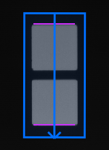
dark to light |
The first edges that separate dark from light (lower to higher gray values) are used for the edge pair. The image on the right shows the edge pair that is found within an ROI if the parameter is set to "dark to light". Because the direction of the ROI is from the top to the bottom, the image is searched for edges top to the bottom of the ROI. The first edge from the top fits the transition criterion of dark to light and is therefore used for the edge pair. The opposite edge is searched from the bottom to the top. In this search direction, also the first edge can be used for the edge pair. All edges between those two edges will be ignored. |
|
|
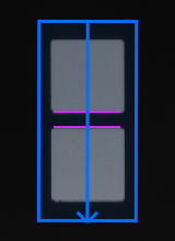
light to dark |
The first edges that separate light from dark (higher to lower gray values) are used for the edge pair. The image on the right shows the edge pair that is found within an ROI if the parameter is set to "light to dark". Because the direction of the ROI is from the top to the bottom, the image is searched for edges top to the bottom of the ROI. The second edge is the first edge that corresponds to the transition criterion of light to dark and is therefore used for the edge pair. The opposite edge is searched from bottom to top. In this search direction, also the second edge is used for the edge pair because it is the first edge that separates light from dark. |
|
|
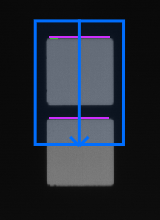
any |
The edges may change in either direction, i.e., from dark to light or from light to dark. The first edges that are found are used for the opposite edge pair, no matter which "Edge Transition" they have. The image on the right shows the edge pair that is found within an ROI if the parameter is set to "any". Because the direction of the ROI is from top to bottom, the image is searched for one edge from top to the bottom of the ROI and the other edge from bottom to top. In this example the first edge that was found searching from top to bottom has the transition "dark to light" whereas the opposite edge that was found in direction from bottom to top has the transition "light to dark". |
|
Additional Parameters
ROI:
This parameter defines the region of interest (ROI) for the processing. By default, "ROI" is defined to be empty. If you want to use an ROI for the processing, you either have to connect the parameter to an appropriate ROI result of a previous tool or you have to draw new ROIs into the image using the available ROI buttons.
The ROI is checked for opposite edges that fit to the current parameter settings, e.g., if the "Edge Transition" is set to "dark to light" the tool searches along the ROI orientation if there is an edge pair whose first edge transits from dark to light. If suitable edge pairs are found, they are used for the measurement.
Alignment Data:
This parameter represents the alignment data that are used to align the ROI. By default no alignment data are connected and thus no effect is visible. If you want to use specific alignment data, you have to connect the parameter to an appropriate result of a previous tool such as Determine Alignment with Matching, Determine Alignment with Straight Border, Align Image, or Rotate Image.
Calibration Data:
This parameter defines the calibration data needed for the correction of possible lens distortions and the position of the camera with respect to the image plane. By default no calibration data are defined. If you want to use calibration data, you have to connect the parameter to an appropriate result of a previous tool, e.g., Calibrate Camera, to make sure that the calibration data are transmitted to this tool. It will be instantly applied to the image.
In case "Calibration Data" are used for this tool, all results that represent pixel values will be automatically transformed to the corresponding world coordinates.
Minimum Edge Completeness:
|
Visualization |
Description |
|---|---|
|
|
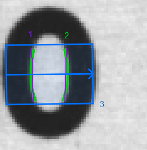
This parameter defines the minimum fraction of the edges (1) that have to be supported by the detected contours (2) inside the ROI (3). If the detected contours account for less than the "Minimum Edge Completeness" of the edges, MERLIC will not establish them. In this case neither the contour nor the edges will be displayed. The contour used for determining the "Minimum Edge Completeness" is detected anywhere inside the ROI. The "Minimum Edge Completeness" is defined as a value between 0 and 1 and can be interpreted as a percentage value from 0% to 100%. It is set to 0.4 by default. An applicable value is automatically determined by easyTouch when an edge is selected. However, you may also adjust the parameter value manually. |
Failed Measurement:
This parameter defines which value is returned in the result "Minimum Distance", "Maximum Distance", "Average Distance", "Edge Completeness", and "Angle" in case no measurement could be performed. The parameter is set to "ignore" by default. You may set the parameter at the corresponding connector to the following values.
|
Value |
Description |
|---|---|
|
ignore |
No value is returned if no measurement could be performed. |
|
−1 |
−1 is returned if no measurement could be performed. You may replace it directly in the input field of the connector with any number or string you want to return. |
|
* |
* is returned if no measurement could be performed. You may replace it directly in the input field of the connector with any number or string you want to return. |
Results
Basic Results
Segments:
This result returns the graphical representation of the edge pair that has been measured. They are returned as segment ROIs. If more than one edge pair has been measured, "Segments" contains the ROIs of all edge pairs.
Average Distance:
This result returns the average distance between the edge pairs. The distance is measured perpendicular to the edge segments and is defined as the mean distance of the "Minimum Distance" and "Maximum Distance". The result is returned in pixels as a real number. In case "Calibration Data" are used, the distance is returned in world coordinates. If more than one edge pair is measured, the corresponding average distances are returned in a tuple.
Angle:
This result returns the angle between the edge pair that has been measured. It is returned in degrees as a real number within the value range from 0° to 180°. If more than one edge pair is measured, the corresponding angles are returned in a tuple.
Tool State:
"Tool State" returns information about the state of the tool and thus can be used for error handling. For more information, see Tool State Result
Additional Results
Minimum Distance:
This result returns the minimum distance between the edge pair. The result is returned in pixels as a real number. In case "Calibration Data" is used, the distance is returned in world coordinates. It is defined as the minimum distance perpendicular to the edge segments. If more than one edge pair is measured, the corresponding minimum distances are returned in a tuple.
Maximum Distance:
This result returns the maximum distance between the edge pair. The result is returned in pixels as a real number. In case "Calibration Data" is used, the distance is returned in world coordinates. It is defined as the maximum distance perpendicular to the edge segments. If more than one edge pair is measured, the corresponding maximum distances are returned in a tuple.
Edge Completeness:
This result returns the actual "Edge Completeness" of the edge pair that has been measured. It is returned as a percentage value in real numbers between 0 and 1. It is an indicator for how much of the contour points of the edges could be used for the measurement. If more than one edge pair is measured, the corresponding "Edge Completeness" values are returned in a tuple.
Used Edges:
This result returns the contours of the edge pair that has been used for the measurement. The returned contour in "Used Edges" might differ from the actual edges in the image, especially when the ROI is very small.
Processing Time:
This result returns the duration of the most recent execution of the tool in milliseconds. The result is provided as additional result. Therefore, it is hidden by default but it can be displayed via the ![]() button beside the tool results. For more information see the section Processing Time in the tool reference overview.
button beside the tool results. For more information see the section Processing Time in the tool reference overview.
Application Examples
This tool is used in the following MERLIC Vision App examples:
- measure_distance_to_center_led.mvapp

