Measure Parallel Edges
Use this tool to measure parallel edges, e.g., to measure the width of an object.
For this tool easyTouch and easyTouch+ are available. This means you may select the edges to be measured interactively in the image while the corresponding parameters are automatically adapted. The tool will insert parallel edges based on the given parameters and edges in the image regardless if they are parallel. Move the mouse pointer over one of the parallel edges you want to measure. MERLIC will display a preview of the region of interest (ROI) and the suggested edge pair contained therein. The position of the mouse pointer influences the search for the corresponding parallel edge, i.e., the parallel edge is determined depending on which side the mouse pointer is positioned. MERLIC searches for a parallel edge at the side on which the mouse is positioned. Thus the preview of suggested edges changes if you move the mouse from one side of the edge to the other. If you want to measure the edges of the easyTouch preview, click on the edge pair to confirm the selection. The parameters are automatically adjusted to fit the selected edges. However, they still can be adjusted manually at the corresponding connectors.
To add further parallel edges to the measurement, you can use easyTouch+, i.e., by pressing the Ctrl key and selecting the additional pair of edges. MERLIC automatically checks if the selected pair of edges fits to the current parameter settings of the previous selection. If they do not fit, e.g., because the mouse hovers over an edge pair with an opposite edge transition, MERLIC gives immediate feedback that the respective edges will be ignored by easyTouch+.
Alternatively, you may use regions of interest (ROIs) for the measuring. If the ROI contains suitable edge pairs that fit the current parameter settings, they are automatically determined and measured. The ROI also determines the start and end point and therefore the length of the edge. Use smaller ROIs to detect edges on a curved line.
Note the different colors of the ROI and the edge pair. The ROI color switches between red and green. It indicates whether the edges within the ROI are unambiguous or not, as shown in the table below.
|
Example |
Description |
|---|---|
|
|
A green highlighted ROI visualizes an unambiguous edge pair. |
|
|
A red highlighted ROI indicates an ambiguous edge pair due to many parallel edges inside the ROI. |
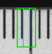
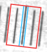
The color of the suggested parallel edges switches between blue and red, as shown below. It indicates the edge transition of the suggested edge pair.
|
Example |
Description |
|---|---|
|
|
The previewed suggested edges are highlighted in blue if no edge pair has been trained before or if the edge transition of the previously trained edge pair matches the edge transition of the currently trained edge pair. |
|
|
When using easyTouch+ a red edge color indicates an opposite edge transition compared to the previously trained one. |

Parameters
Basic Parameters
Image:
This parameter represents the input image in which the parallel edges are measured.
If a color image is used as input image for this tool, only the first channel, i.e., the red channel, is used for the processing.
Edge Contrast:
This parameter defines the contrast of the parallel edges relative to the background. The parameter is defined as gray values and set to 10 by default. When a parallel edge pair is selected for the measuring, the "Edge Contrast" of this edge pair is instantly determined and adopted. If further parallel edge pairs are added using easyTouch+, the "Edge Contrast" is adjusted automatically with each edge pair that is added to the selection. However, you may also change its value manually at the corresponding connector.
Edge Width:
This parameter defines the width of the edges. It is defined in pixels and set to 2 px by default. When an edge pair is selected for measuring, the "Edge Width" of its edges is instantly determined and adopted. If further parallel edges are added using easyTouch+, the "Edge Width" is adjusted automatically with each edge pair that is added to the selection. However, you may also change its value manually at the corresponding connector.
Edge Transition:
This parameter defines the transition property of the edge pair. The transition is determined from inside to outside. The parameter is set to "any" by default. When an edge pair is selected for measuring, the "Edge Transition" is instantly determined and adjusted automatically for each edge pair that is added to the selection.
The "Edge Transition" is determined depending on which side of the edge segment the mouse pointer is positioned and thus on which side a parallel edge is searched. If the mouse is positioned at the side with the higher gray values, the "Edge Transition" is determined as "dark to light" since the transition is determined in the direction from outside to inside. Thus the position of the mouse pointer also influences how the value is determined by easyTouch.
|
Value |
Description |
|---|---|
|
light to dark |
The edges of the edge pair change from light to dark, i.e., the edges change from higher to lower gray values. If this value is set, only edges with this transition property are measured. Other edge pairs are excluded from the measurement. |
|
dark to light |
The edges of the edge pair changes from dark to light, i.e., the edges change from lower to higher gray values. If this value is set, only edges with this transition property are measured. Other edge pairs are excluded from the measurement. |
|
any |
The edges of the edge pair may change in either direction, i.e., the edges may change from higher to lower gray values and from lower to higher gray values. If this value is set, all edge pairs are included in the measurement. |
Additional Parameters
ROI:
This parameter defines the region of interest (ROI) for the processing. By default, "ROI" is defined to be empty. If you want to use an ROI for the processing, you either have to connect the parameter to an appropriate ROI result of a previous tool or you have to draw new ROIs into the image using the available ROI buttons.
The ROI is checked for parallel edges that fit to the current parameter settings, e.g., if the "Edge Transition" is set to "dark to light" the tool searches along the ROI orientation if there are parallel edges that change from dark to light. If suitable edges are found, they are used for the measurement.
Alignment Data:
This parameter represents the alignment data that are used to align the ROI. By default no alignment data are connected and thus no effect is visible. If you want to use specific alignment data, you have to connect the parameter to an appropriate result of a previous tool such as Determine Alignment with Matching, Determine Alignment with Straight Border, Align Image, or Rotate Image.
Calibration Data:
This parameter defines the calibration data needed for the correction of possible lens distortions and the position of the camera with respect to the image plane. By default no calibration data are defined. If you want to use calibration data, you have to connect the parameter to an appropriate result of a previous tool, e.g., Calibrate Camera, to make sure that the calibration data are transmitted to this tool. It will be instantly applied to the image.
In case "Calibration Data" are used for this tool, all results that represent pixel values will be automatically transformed to the corresponding world coordinates.
Failed Measurement:
This parameter defines which value is returned in the result "Object Width" in case no measurement could be performed. The parameter is set to "ignore" by default. You may set the parameter at the corresponding connector to the following values.
|
Value |
Description |
|---|---|
|
ignore |
No value is returned if no measurement could be performed. |
|
−1 |
−1 is returned if no measurement could be performed. You may replace it directly in the input field of the connector with any number or string you want to return. |
|
* |
* is returned if no measurement could be performed. You may replace it directly in the input field of the connector with any number or string you want to return. |
Results
Basic Results
Parallel Edges:
This result returns the graphical representation of the parallel edges that have been measured. They are returned as an rectangle ROI in which the ROI borders, perpendicular to the ROI orientation arrow, represent the parallel edges.
Object Width:
This result returns the distance between the parallel edges that have been measured. The result is returned in pixels as a real number. In case "Calibration Data" is used, the distance is returned in world coordinates. If more than one parallel edge pair is measured, the corresponding widths are returned in a tuple.
Tool State:
"Tool State" returns information about the state of the tool and thus can be used for error handling. For more information, see Tool State Result
Additional Results
Processing Time:
This result returns the duration of the most recent execution of the tool in milliseconds. The result is provided as additional result. Therefore, it is hidden by default but it can be displayed via the ![]() button beside the tool results. For more information see the section Processing Time in the tool reference overview.
button beside the tool results. For more information see the section Processing Time in the tool reference overview.
Application Examples
This tool is used in the following MERLIC Vision App examples:
- measure_distance_to_center_led.mvapp

