Measure Outliers
Use this tool to measure the distance from an edge to a fitted segment, e.g., to measure outliers of an edge.
For this tool easyTouch is available. This means you may select the edge to be measured interactively in the image while the corresponding parameters are automatically adapted. Move the mouse over an edge you want to measure. MERLIC will display a preview of the suggested edge. If you want to measure the previewed edge, click on the edge to confirm the selection. The parameters are automatically adjusted to fit the selected edge. Furthermore a line segment is fitted to the selected edge. This line segment serves as a distance reference, i.e., outliers are determined by measuring the distance between the reference segment and the edge. You can make further adjustment by changing the parameter values manually at the corresponding connectors.
Alternatively you may use a region of interest (ROI) for the measuring. Draw an ROI into the image. If the ROI contains a possible edge that fits the current parameter settings, it is automatically determined and measured.
Parameters
Basic Parameters
Image:
This parameter represents the input image in which the outliers are measured.
If a color image is used as input image for this tool, only the first channel, i.e., the red channel, is used for the processing.
Edge Contrast:
This parameter defines the contrast of the edge relative to the background. The parameter is defined as gray values and set to 10 by default. When an edge segment is selected for measuring, the "Edge Contrast" of this segment is instantly determined and adopted. However, you may also change its value manually at the corresponding connector.
Edge Width:
This parameter defines the width of the edge segment to be measured. It is defined in pixels and set to 2 px by default. When an edge segment is selected for measuring, the "Edge Width" of this segment is instantly determined and adopted. However, you may also change its value manually at the corresponding connector.
Edge Transition:
This parameter defines the transition property of the edge segment to be measured. The transition is determined from outside to inside. The parameter is set to "light to dark" by default. When an edge pair of a reference object in row spacing is selected for measuring, the "Edge Transition" is instantly determined.
The "Edge Transition" is determined depending on which side of the edge segment the mouse pointer is positioned. If the mouse is positioned at the side with the higher gray values, the "Edge Transition" is determined as "light to dark" otherwise "dark to light". Thus the position of the mouse pointer also influences how the value is determined by easyTouch.
|
Value |
Description |
|---|---|
|
light to dark |
The edge segment changes from light to dark, i.e., the edges change from higher to lower gray values. If this value is set, only edges with this transition property are measured. Other edge pairs are excluded from the measurement. |
|
dark to light |
The edge segment changes from dark to light, i.e., the edges change from lower to higher gray values. If this value is set, only edges with this transition property are measured. Other edge pairs are excluded from the measurement. |
Additional Parameters
ROI:
This parameter defines the region of interest (ROI) for the processing. By default, "ROI" is defined to be empty. If you want to use an ROI for the processing, you either have to connect the parameter to an appropriate ROI result of a previous tool or you have to draw new ROIs into the image using the available ROI buttons.
The ROI is checked for an edge that fit the current parameter settings, e.g., if the "Edge Transition" is set to "dark to light" the tool searches along the ROI orientation if there is an edge that changes from dark to light. If suitable edges are found, they are used for the measurement.
Alignment Data:
This parameter represents the alignment data that are used to align the ROI. By default no alignment data are connected and thus no effect is visible. If you want to use specific alignment data, you have to connect the parameter to an appropriate result of a previous tool such as Determine Alignment with Matching, Determine Alignment with Straight Border, Align Image, or Rotate Image.
Calibration Data:
This parameter defines the calibration data needed for the correction of possible lens distortions and the position of the camera with respect to the image plane. By default no calibration data are defined. If you want to use calibration data, you have to connect the parameter to an appropriate result of a previous tool, e.g., Calibrate Camera, to make sure that the calibration data are transmitted to this tool. It will be instantly applied to the image.
In case "Calibration Data" are used for this tool, all results that represent pixel values will be automatically transformed to the corresponding world coordinates.
Distance Reference:
This parameter defines the distance reference for the measurement. It is used to determine if the distance to the selected edge is measured from a fitted segment or from one border segment of the ROI. It is set to "fitted segment" by default. If you want to change the "Distance Reference", select your preferred reference line using the available options of the corresponding connector. The following table contains a description of the available values for "Distance Reference" together with example images that show which segment is used for the respective values.
|
Value |
Description |
Example image |
|---|---|---|
|
fitted segment |
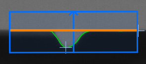
The distance reference is a segment that is fitted to the selected edge. In the example image on the right the fitted segment that is used as distance reference is marked by the orange line for a better understanding. The selected edge is visualized in green within the ROI. The distances to the detected edge are measured perpendicular to the fitted segment. They are returned with an algebraic sign. Edge points below the fitted segment have a negative sign and edge points above the segment have a positive sign. |
|
|
ROI |
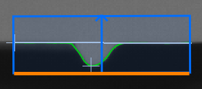
The distance reference is a border segment of the rectangular ROI that is inserted automatically, when an edge is selected for the measure. In the example image on the right the ROI border segment that is used as distance reference is marked by the orange line whereas the resulting "Fitted Segment" is visualized in green. The distance to the edge is measured from the ROI border segment along the direction of the ROI orientation. |
|
Failed Measurement:
This parameter defines which value is returned in the result "Lower Outlier Distance", "Upper Outlier Distance", "Edge Completeness", "Straightness", and "Average Distance" in case no measurement could be performed. The parameter is set to "ignore" by default. You may set the parameter at the corresponding connector to the following values.
|
Value |
Description |
|---|---|
|
ignore |
No value is returned if no measurement could be performed. |
|
−1 |
−1 is returned if no measurement could be performed. You may replace it directly in the input field of the connector with any number or string you want to return. |
|
* |
* is returned if no measurement could be performed. You may replace it directly in the input field of the connector with any number or string you want to return. |
Results
Basic Results
Edge:
This result returns the contour of the selected edge whose outliers have been measured.
Lower Outlier:
This result returns the point on the selected edge that represents the lower outlier. In case the "Distance Reference" is set to "fitted segment", the furthest outlier in the negative direction of the ROI is returned. If the "Distance Reference" is set to ROI, the outlier that is nearest to the reference side of the ROI is returned. The distance between the "Lower Outlier" and the "Distance Reference" is measured perpendicular to the "Distance Reference". The result is returned as a point ROI. It is visualized in the image by a cross as displayed in the example images in the description of the parameter "Distance Reference".
Upper Outlier:
This result returns the point on the selected edge that represents the upper outlier. In case the "Distance Reference" is set to "fitted segment", the furthest outlier in the positive direction of the ROI is returned. If the "Distance Reference" is set to ROI, the outlier that is most distant to the reference side of the ROI is returned. The distance between the "Upper Outlier" and the "Distance Reference" is measured perpendicular to the "Distance Reference". The result is returned as a point ROI. It ist visualized in the image by a cross as displayed in the example images in the description of the parameter "Distance Reference".
Lower Outlier Distance:
This results returns the signed distance between the "Lower Outlier" and the predefined "Distance Reference". The result is returned in pixels. as a signed real number. In case "Calibration Data" is used, the distance is returned in world coordinates.
Upper Outlier Distance:
This results returns the signed distance between the "Upper Outlier" and the predefined "Distance Reference". The result is returned in pixels. as a signed real number. In case "Calibration Data" is used, the distance is returned in world coordinates.
Tool State:
"Tool State" returns information about the state of the tool and thus can be used for error handling. For more information, see Tool State Result
Additional Results
Fitted Segment:
This result returns the graphical representation of the segment that is fitted to the selected edge. The result is returned as a segment ROI
Average Distance:
This result contains the average of the absolute distance between the selected edge and the predefined "Distance Reference". It is always a positive value. The result is returned in pixels as a real number. In case "Calibration Data" is used, the distance is returned in world coordinates.
Edge Completeness:
This result contains the "Edge Completeness" of the edge whose outliers have been measured. It is defined as a real number between 0 and 1 and is an indicator how much the contour of the edge is disturbed. The higher the value the less disturbances are in the edge and the higher is the edge completeness.
Processing Time:
This result returns the duration of the most recent execution of the tool in milliseconds. The result is provided as additional result. Therefore, it is hidden by default but it can be displayed via the ![]() button beside the tool results. For more information see the section Processing Time in the tool reference overview.
button beside the tool results. For more information see the section Processing Time in the tool reference overview.

