Success Story
Cellular dielectric spectroscopy (CDS) is an impedance-based measurement technique that measures the changes in electrical impedance relative to a voltage applied to a layer of cells in which no cell is growing on top of another. Eliminating the need for tags, dyes, or specialized reagents, the technique relies on the fact that specific cell receptors or glycoproteins of the cell's plasma membrane have binding sites for specific adhesion molecules.
By activating these receptors using antibodies or artificial reagents, morphological cellular changes occur that affect the changes in current flow across the cell. Measuring the changes in impedance of a voltage applied across the cells can then be used to indicate the level of binding at specific receptors, a particularly useful measurement for drug development.
To perform these measurements, companies such as MDS Analytical Technologies, now part of Danaher Corp., build systems that automatically apply different reagents to cells and measure their impedance using the CDS technique. The company's CellKey 384 system, for example, is designed for cell-based kinetic screening of 384-well microtiter plates processing up to 24,600 wells in eight hours.
"To properly measure the impedance in each of the microtiter wells," says Uwe Trautenbach, manufacturing engineering manager at Conductive Technologies, "the conductance at each well must be measured." As a third-tier supplier to the pharmaceutical industry, Conductive Technologies manufactures these 384-well microtiter plates equipped with electrochemical sensors specifically for these tasks.
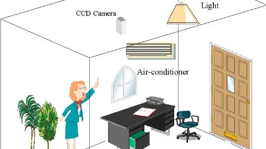
To properly image the 5 × 3.5-in. electrode cards, they are first placed in a fixture that is located on the surface of a 5 × 5-in. white fiberoptic backlight from Volpi. Driven by an IntraLED 2020 white LED light source, also from Volpi, this backlight provides a homogenous 5.6-Mlux illumination of the electrode card surface and is controlled from the serial port of the host PC.
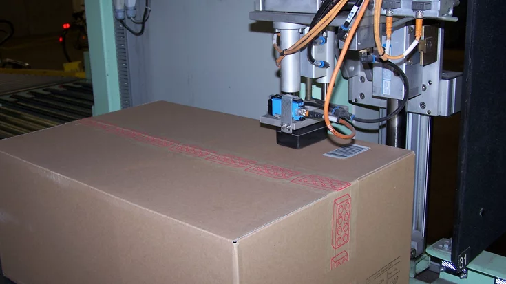
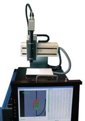
After the electrode card is placed in position, all 384 electrodes must be imaged. To roughly locate the electrodes' position in the field of view, a PicSight 202N CCD GigE Vision camera from Leutron Vision is mounted onto the horizontal axis of an x-y-z Cartesian robot from Fisnar.
"Coupling the 1624 × 1236[-pixel] CCD camera with a 90-mm VZM 450i lens from Edmund Optics allows the camera to image the 100-µm spacing between the electrodes to a repeatable accuracy of ±5%," says Trautenbach. By using Robot Edit software running on Windows XP Pro, the path of the robot and camera focusing are programmed to locate the approximate position of each electrode. After the robot travels to a specific location, the camera system is triggered to image the electrode site using an 8012 low-profile PCI digital interface card from Sealevel Systems.
This provides eight Reed relay outputs (SPST) and eight optically isolated inputs that are used to drive the robot and trigger the camera system. After images of the electrodes are captured by the camera, they are transferred over the GigE Vision interface to host PC memory and displayed on an LCD monitor. "To analyze the shape of the electrodes within the image, the captured image is first compared with a known good master image that is stored as a bitmap file in the host PC," explains Trautenbach. This is performed using the HALCON image-processing and machine-vision software package from MVTec Software GmbH.
A 384-well microtiter plate without bases made of polycarbonate must be connected to an array of 384 electrodes, which in turn is connected to an array of contact pads. When manufacturing an electrode array, PET cards made of polyethylene terephthalate coated with a gold film are first ablated by laser to obtain an array of electrodes.
After the electrodes have been manufactured, contact pads for each electrode are printed onto the film together with spacer bars. However, before the prepared sensor array and contact pads can be applied to the polycarbonate plate, each individual electrode must first be tested to ensure that it is functioning properly.
“Some post-processing procedures on the electrode module carry a high risk of damaging the vapor-deposited gold coating on the PET film,” explains Trautenbach. “Defective chips must be sorted out, as incorrect values render the finished test chip unusable.”
Therefore, each of the two individual electrodes, which are spaced 100 µm apart and used in each cavity of the 384-well microtiter plates, must be tested individually. If, for example, the electrodes fuse together, it becomes impossible to measure impedance correctly. If, on the other hand, the electrodes are too close together or too far apart, the impedance measurement will be incorrect.
In the past, these electrode fingers had to be checked manually by employees using microscopes. “This was, of course, an extremely strenuous task, even for experienced technicians. And, due to the human component, it was also very prone to error,” explains Trautenbach. Against this background, Trautenbach and his colleagues developed a semi-automatic system that can test microtiter electrode chips at a rate of 10 chips per hour.
Conductive Technologies' PC-based system uses standard lenses, lighting systems, I/O cards, and industrial image processing software in combination with a commercially available Cartesian robot.
Once a finished product has been successfully tested, it is delivered to companies such as Danaher, where the microtiter chips are filled using the CellKey system and measurements are performed using the assembled contact pads on the finished electromechanical chips.
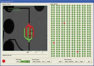
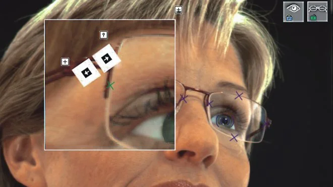
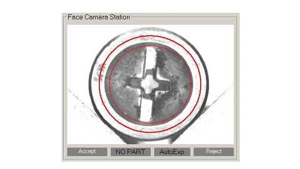
"After the images are compared, a known good region of interest (ROI) can be isolated within the captured image to locate the electrode pair," says Trautenbach. Once the ROI is located, it is then thresholded to highlight the gold electrodes from the PET film background of the electrode card. Once extracted, the morphology of the electrodes can be examined.
"Within the ROI there should be only two electrodes," notes Trautenbach. "Thus, counting the number of connected pixel areas within the ROI should return a value of just two connected regions. If, for example, the system returns a value of one, then the electrodes may be fused and may be rejected. If the system returns a result of more than two, the electrodes may be damaged.
" After determining the presence of a single pair of electrodes, area measurements of the electrodes are performed, again using HALCON to determine correct impedance measurements will be made. "By measuring this electrode area within specific predetermined values, pass/fail criteria can be established. This is also used to determine whether a pass/fail decision should be logged or flagged to the operator. "Although programming the vision system only took a few days inside the HALCON 8.0 vision application development environment," says Trautenbach, "most of the programming development was spent on the Visual Basic (VB) 6.0-based user interface, logic, and robotics handling."
After the vision algorithms were completed, they were then exported with a built-in HALCON software tool and embedded in the Visual Basic software development kit (SDK). Besides image acquisition and processing, VB also supports the host user interface and logic for the I/O and CNC robot. After each individual electrode card is tested, the results are displayed on the LCD monitor. From this screen the operator can recall and view any electrode pair images that are flagged as possible failures and perform a final pass/fail decision on the part. Alternatively, as the system inspects each individual electrode pair, the operator can program the system to stop and display any potential faults as they are being inspected. "In this way," says Trautenbach, "the operator can determine any faults and reject a part before the entire electrode array is analyzed."
Costing approximately $65,000, Conductive Technologies has developed the system primarily for its own internal testing of microtiter electrode arrays.
Author: Andy Wilson
Article kindly provided by Vision Systems Design. All product names, trademarks and images of the products/trademarks are copyright by their holders. All rights reserved.