Success Story
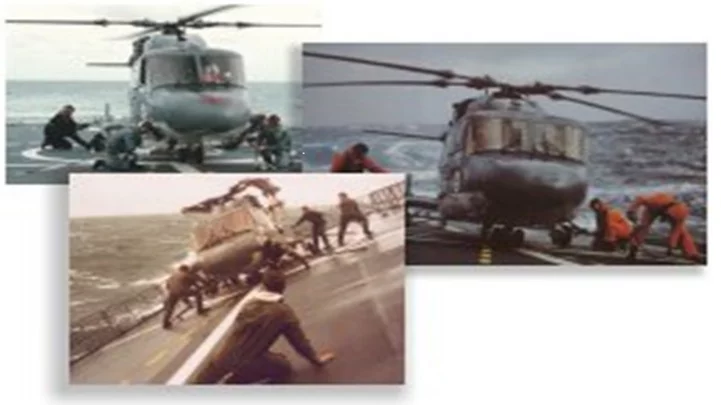
Traditionally, rail infrastructure has been inspected manually by foot patrols walking the entire length of a rail network to visually determine whether any flaws exist that could result in failures. Needless to say, the method is extremely labor intensive and time consuming.
To minimize the disruption to train services, the manual inspection process is usually performed overnight and at weekends. However, due to the increase in passenger and freight traffic on rail networks, the time that can be allocated to access the rail infrastructure by foot patrols is now at a premium. Hence rail infrastructure owners are under pressure to find more effective means to perform the task. To reduce the time required to inspect its rail network, UK infrastructure owner Network Rail (London, England) is now deploying a new vision-based inspection system that looks set to replace the earlier manual inspection process. Not only will the system help to increase the availability -- and assure the safety -- of its rail network, it will also enable the organization to determine the condition of the network with greater consistency and accuracy.
Developed by Omnicom Engineering (York, UK), the OmniVision system has been designed to automatically detect the same types of flaws that would be spotted by foot patrols. These include missing fasteners that hold the rail in place on sleepers and faults in weak points in the infrastructure such as at rail joints where lengths of rail are bolted together.
The system will also detect the scarring of rail heads, incorrectly fitted rail clamps and any issues with welds that join sections of rail together to form one continuous rail.
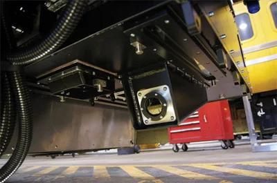
The OmniVision system comprises an array of seven 2048 x 1 pixel line scan cameras, four 3D profile cameras, a sweeping laser scanner and two thermal cameras. Fitted to the underside of a rail inspection car, the vision system illuminates the rail with an array of LED line lights and acquires images of the track and its surroundings as the car moves down the track at speeds of up to 125mph (Figure 1). The on-board vision system is complemented by an off-train processing system located at the Network Rail in Derby that processes the data to determine the integrity of the rail network.
For every 0.8mm that the inspection vehicle travels, a pair of three line scan cameras housed in rugged enclosures capture images of each of the rail tracks. Two vertically positioned cameras image the top surface or the head of each of the rails, while the other four are positioned at an angle to capture images of the web of the rail. A seventh centrally-located line scan camera captures images of the area between the two rails from which the condition of the ballast and the rail sleepers and the location and condition of other rail assets that complement the signaling system can be determined. The cameras transfer image data to frame grabbers in a PC-based 19in rack system on board the train over a Camera Link interface. The frame grabbers were designed in-house to ensure that the data transfer rate from the cameras could be maintained at a rate of approximately 145MBytes/s and that no artifacts within the images are lost through compression.
Once captured, the images from each of the cameras are then written to a set of 1TByte solid state drives. Within the same rugged enclosure as the line scan cameras, the pair of thermal cameras mounted at 45° angles point to the inside web of each of the rails. Their purpose is to capture thermal data at points such as rail joints which can expand and contract depending on ambient temperature. Both the thermal cameras are interfaced via GigE connections to a frame grabber in the on-board 19in rack and the images from them are also stored on 1TByte solid state drives. Further down the inspection vehicle, two pairs of 3D profile cameras capture a profile of the rails and the area surrounding them for every 200mm that the vehicle travels. Data from the four cameras are transferred to the 19in rack-mounted system over a GigE interface to a dedicated frame grabber and the data again stored on TByte drives. Data acquired by the cameras is used to build a 3D image of the rails and the fasteners used to hold the rails to the sleepers and the ballast around them.
In addition to the line scan, thermal and 3D profile cameras, the system also employs a centrally-mounted sweeping laser scanner situated on the underside of the inspection vehicle which covers a distance of 5m on either side of the rails. Data from the laser scanner - which is transferred to the 19in rack-mounted system over an Ethernet interface and also stored on a set of Terabyte drives - is used to determine whether or not the height of the surrounding ballast on the rail is either too high or deficient.
In operation, a vehicle fitted with the imaging system acquires around 5TBytes of image data in a single shift over a distance of around 250 miles. Once acquired, the image data from all the cameras is indexed with timing and GPS positional data such that the data can be correlated prior to processing. Data acquired from the cameras during a shift is then transmitted to the dedicated processing environment at Network Rail, where it is transferred onto a 500TByte parallel file storage system at an aggregate data rate of around 2GB/s for a single data set.
Because the image data is tagged with the location and time at which it was acquired, it is possible to establish the start and end of a specific patrol, or part of a single shift. The indexed imagery associated with each patrol is then subdivided into sections representing several hundred meters of rail infrastructure, after which it is farmed out to a dedicated cluster set of Windows-based servers, known as the image processing factory. Once one set of image data relating to one section of rail has been analyzed by the processing cluster of 20 multi-core PC-based servers and the results returned, a following set of data is transferred into the processors until an entire patrol has been analyzed. To process the images acquired by the cameras, the OmniVision system uses the image processing functions in MVTec's (Munich, Germany; www.mvtec.com) HALCON software library. Typically, the images acquired by the line scan cameras are first segmented to determine regions of interest - such as the location of the rail.
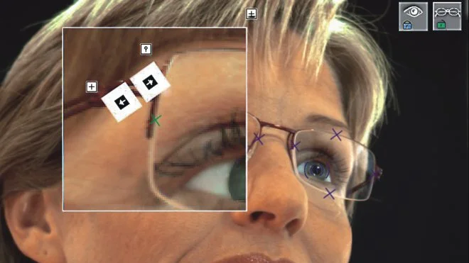
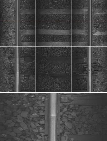
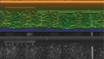
Once the location of the rail has been found, it is possible to establish an area of interest around the rail where items such as fasteners, clamps and rail joints should be located. A combination of edge detection and shape-based matching algorithms are then used to determine whether a fastener, clamp or rail joint has been identified by comparing the image of the objects with models stored on the database of the system (Figure 2). To verify that objects such as fasteners or clamp are present, missing, or being obscured by ballast, a more detailed analysis is performed on the data acquired by the 3D profile cameras as a secondary check. To do so, the 3D profile data is analyzed using HALCON's 3D pattern matching algorithm to determine the 3D position and orientation of the objects even if they are partially occluded by ballast (Figure 3). Should the software be unable to match the 3D data with a 3D model of the object, the potential defect - known as a candidate - is flagged for further analysis and returned to a database for manual verification.
The system can also determine the condition of welds in the rail. As the vision inspection system moves over each of the welds, the line scan cameras capture an image of each one. From the images, the software can perform shape-based matching to identify locations where a potential joint failure may exist. Any potential failure of the weld is also flagged as a potential candidate for further investigation. Similarly, the 3D-based model created from data captured by the laser scanner can also be analyzed by the software to determine if the height of the ballast in and around the track is within acceptable limits.
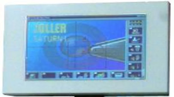
Through OmniVision's Viewer application - which runs on a set of eight PCs connected to the server - track inspectors are visually presented with a breakdown of the defects along with the images associated with them. This allows them to navigate through, review and prioritize any defects that the system may have detected. Once a defect has been identified, the operators can then schedule the necessary repairs to be carried out manually by on-track teams. To date, three Omnicom vision systems have been fitted to Network Rail inspection vehicles and effectively used to determine the condition of the UK's West Coast mainline network. Currently, two additional systems are being commissioned and by the end of this year, Network Rail plans to roll the system out to cover the East Coast main line between London and Edinburgh and the Great Western mainline from London to Wales. When fully operational, the fleet of inspection vehicles will inspect more than 15,000 miles of Network Rail's rail network per fortnight, all year round.
Author: Steven Tait.
Article kindly provided by Vision Systems Design. All product names, trademarks and images of the products/trademarks are copyright by their holders.
All rights reserved.