Success Story
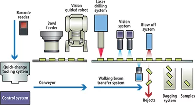
When a manufacturer of small plastic parts used in gas detectors for the mining industry required a new machine to automate the laser drilling of holes in such parts, it approached laser specialists ES Technology Limited (Oxford, England) to build one specifically for the purpose. In turn, ES Technology enlisted the help of machine builders at RNA Automation (Birmingham, England) and their partner Fisher Smith (Kettering, England) that developed a vision system for the machine to enable the parts to be automatically inspected, ensuring that the holes had been accurately drilled. No fewer than eleven different variants of plastic parts needed to be inspected, drilled with holes that varied in diameter from 15-50µm. The system was required to accommodate all the variants - inspecting each one to determine its position, and the entry and exit sizes of holes in the plastic. In addition, it needed to be flexible enough to enable an operator to change the tooling of the parts between each of the component runs. The system incorporates a bowl feeder into which parts of a specific batch type are loaded. A vision-guided robotic system then identifies the part and places it onto a fixed position on a walking beam transfer system.
A UV laser drilling system then drills hour glass-shaped holes into the part, after which the part is moved through three further vision stations where they are inspected. Having done so, parts are transferred over two bins where they are either accepted or rejected (Figure 1).
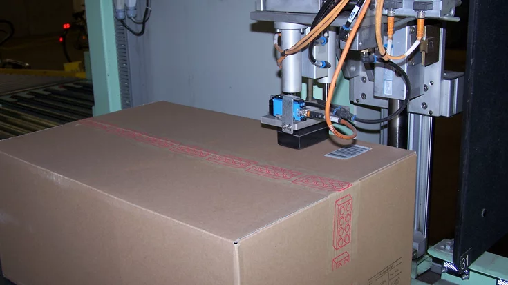
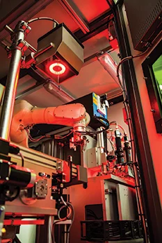
Due to the variety of plastic parts to be produced, a system was developed to enable an operator to change the tooling on the machine to accommodate different product runs. To do so, a Mitsubishi (Tokyo, Japan) PLC - that controls the entire operation of the machine - was programmed to identify a unique barcode associated with each batch of product to be produced. After the barcode is scanned, tooling setup parameters for a specific type of component that were previously programmed and stored on the PLC are displayed to the user on a touch screen interface. These indicate to the operator what type of tooling should be fitted to both the bowl feeder and the walking beam system. In addition, the PLC can automatically recognize if incorrect sets of tooling are fitted, eliminating the risk of inadvertent human errors. A fully-validated tool changeover to accommodate a different plastic part can be accomplished in less than 5 min., resulting in improved uptime and productivity. Once the correct tooling is fitted to the machine, it is ready to drill and inspect the parts. Before the process commences, the raw plastic components are first loaded into an RNA vibratory bowl feeder which shakes the parts onto a linear conveyor. A Kawasaki (Warrington, England) six-axis robot then picks the parts from the conveyor and places them into the first fixture of a walking beam system which in turn uses pneumatic grippers to sequentially transfer each part from the linear conveyor under the first of a series of vision stations (Figure 2). Prior to laser drilling, it was important to ensure that the Kawasaki robot picked the parts from the linear conveyor and correctly oriented each one before transferring it to the walking beam system. To do so, Fisher-Smith GenVis software running on a PC was trained to create templates of each of the plastic parts using MVTec's (Munich, Germany) HALCON shape-based matching algorithm.
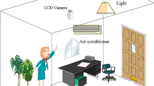
At the first of the vision stations, an image of the part to be inspected is captured by an Ace 2048 x 2048 4Mpixel monochrome camera from Basler (Ahrensburg, Germany) fitted with a 50mm lens as it is illuminated by a RK2036-R ring light from Vision & Control (Würzburg, Germany). The image is then transferred to the PC over a GigE interface where the software matches the image to the template. In the process, the software determines the location of key features found in the image of the part and by how much they are rotated compared to the template. The PC then calculates the positional and rotational transformation that is necessary to ensure that the robot can pick up the part and place it into the walking beam system at the correct orientation prior to drilling. Finally, the positional and rotational data is transferred to the robot controller from the PC over an Ethernet interface. In certain instances, when plastic parts are too close to one another on the conveyor, it may be impossible for the end effecter on the robot head to pick up a single part, due to potential collisions of the effecter with the parts. To circumvent this, blob analysis is performed to determine that the area around the part to be picked is clear. If it is not, the part is deemed to be unable to be effectively retrieved from the line by the robot and the robot indexes the conveyor so the part is recycled back into the bowl by a return conveyor. Bowl tooling avoids most of these situations to ensure a high collection rate of parts from the conveyor. Once the robot has picked up a part and oriented it correctly, it is placed in the walking beam transfer system that ensures that the part will remain correctly orientated as it moves through the drilling and inspection process. The part is then moved under the UV laser drilling system supplied by ES Technology which creates the hourglass-shaped hole in the plastic material using a 12W diode pumped UV laser from Lee Laser (Orlando, FL, USA). After the component is drilled, the component is lifted by the walking beam and moved to the next vision station for inspection.
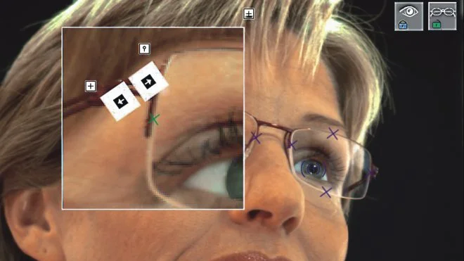
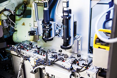
At the second vision station, the component is inspected again to determine the location of the drilled hole, ensuring that no rotational errors were introduced before the drilling process. To do so, the part is illuminated from above by a Vision & Control RK2036-R ring light and an image of it captured using a second Basler 2048 x 2048 monochrome 4 Mpixel camera fitted with a Vision and Control T-107 telecentric lens. The image is then transferred to the PC over a GigE interface where a shape recognition algorithm identifies the part. Next, a thresholding algorithm determines the location of the hole and the 2D co-ordinates of the hole are measured. Once the system has determined whether the hole has been drilled in the correct location, the walking beam system moves the part to a further two vision inspection stations. Here, the size of the hole at its point of entry and its size at its point of exit are measured. These are two critical features that affect how accurately any sensor fitted with the part will operate. At the vision entry hole measurement station, the part is illuminated by another Vision & Control RK2036-R ring light and an image of the top surface captured by a second Basler Ace 2048 x 2048 4 Mpixel monochrome camera fitted with a Vision & Control x 20 magnification telecentric lens which provides a 1.2mm field of view and a 5µm depth of view. Measuring the size of the holes presented a challenge because the aperture in the plastic itself is hourglass-shaped and each of the plastic parts can vary in thickness by 100µm and the placement of the part can introduce further small height errors. To overcome the difficulties posed by the unique shape, the potential variation in thickness of the parts and the limited depth of view of the camera, the camera was fitted to a servo driven precision ball screw slide from Physik Intrumente (Bedford, England).
Once the part enters the entry/exit inspection station, Fisher-Smith's own Genvis software running on the PC instructs the slide to move the camera vertically in 5µm increments from a pre-programmed starting position. The camera is then triggered to capture sixty consecutive images of the top surface of the part as the slide moves the camera over a vertical distance of 300µm in 5µm increments. To control the servo drive to accommodate the variety of parts to be inspected, the servo is interfaced to the PC-based vision system via an RS-232 interface. This allows the start and end points of the image acquisition process to be defined for each part by the Genvis software.
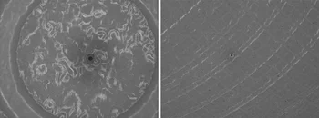
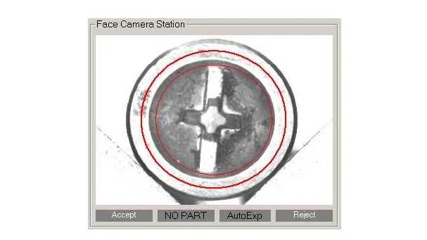
The 60 images acquired by the GigE camera are transferred over the GigE interface for analysis by the HALCON image analysis algorithms running in the GenVis PC-based software environment to determine the size of the hole at its nominal entry point. The software analyzes each of the 60 images to find which one of them contains an image of the entry hole that is optimally focused. This is accomplished by detecting the changes in gray scale intensity around the circumferential edges of the hole from which it produces a gradient map. When one of the images captured by the camera is in focus, the directional change in the intensity gradient at will be higher for that image. Therefore, by finding the image with the highest intensity gradient out of the 60 images, the software can determine which of the images is in focus. Having done so, an edge detection algorithm is then employed to determine the specific size of the hole in that image (Figure 3). Once the size of the entry hole has been determined, the walking beam system transfers the part to a final vision inspection station. Here, the part is illuminated by a third Vision and Control RK613-R ring light, and an identical vision system with yet another Basler camera mounted on a slide underneath the walking beam captures a further 60 images of the bottom of the part. For some parts the surface at the exit point is so rough that front illumination is not possible. In this case a Vision & Control RAL10-7-R spotlight is used above the part to create a silhouette of the hole. Sixty images are again transferred to the PC over a GigE interface where the size of the hole in the bottom of the part is determined in a similar fashion (Figure 3) by the HALCON software. Having inspected the part, the walking beam moves it to the end of the walking beam over a pass or reject chute. At this point, all the various pass or fail results acquired from the hole position, entry hole and exit hole cameras at the vision stations have been aggregated by the PLC, which then instructs the walking beam to release the grippers it uses to hold the part, dropping the part into one of the two chutes. To provide the manufacturer with details of the results of the inspection procedure, all the inspection parameters associated with each part are collated on the PC and stored on disk, where the data can be output as a .csv file into the manufacturer's own Minitab (State College, PA, USA) Statistical Process Control (SPC) system. By analyzing the data for quality control purposes, the manufacturer can thereby be assured that the system is always working at its full potential and also use such information to maintain and improve the upstream process.
Author: Robert Fisher.
Article kindly provided by Vision Systems Design. All product names, trademarks and images of the products/trademarks are copyright by their holders.
All rights reserved.