Circuit Breakers – Sensata
Electric Components | Glass, Metal, Paper, Foil & Printing | Blob Analysis | Filtering | Matching | MeasuringGigE camera, special oven, and image-processing algorithms test snap point of bimetal disks.

Hair dryers can consume up to 1875 W of power to produce hot-air flow up to 140°F, or the maximum temperature the typical human scalp can handle without burning. That's a lot of electrical energy, producing a lot of heat. A bimetallic disk, measuring about 5 × 10 mm, forms the heart of a thermal protector switch that breaks the electrical circuit if the internal temperature exceeds a safe level.
Sensata Technologies manufactures bimetal disks and thermal protector switches for many products, including coffee machines and electric motors. As a bimetal disk is heated, the two metal layers expand at different rates. Eventually, the disk will bend enough to break a physical connection with a nearby electrode, cutting power to the circuit. After the device cools sufficiently, the disk returns to its original shape, and the circuit can be energized.
Until recently, Sensata had used either oil baths or heating ovens with thermal imaging systems to heat the disks and measure the "snap" level, or the temperature at which the disk makes a relatively fast, hard movement. Unfortunately, environmental concerns and rising petroleum costs have made oil baths less attractive as a heating/testing medium, while the highly reflective bimetal disks must be coated before thermal imaging can make accurate measurements.
In an effort to alleviate these problems, Sensata turned to machine-vision specialist TCPM to develop a system using traditional visible-light sensors, special ovens, and a generic PC running a Visual Basic front end and MVTec Software HALCON image-processing algorithms to test up to 1024 bimetal disks per hour with greater accuracy and speed than previous test methods.

Snap off the power
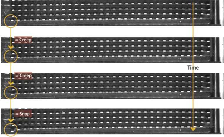
Bimetal disks are made by bonding two different metal sheets together and then stamping out the disk. Individual disks are welded to a "slug," which represents one electrode in the thermal protector switch. When the disk and slug are enclosed in a thermal protector switch housing, the bimetal disk rests against the other electrode, or "contact." As ambient temperatures increase, the bimetal disk begins to stretch, with one metal layer stretching faster than the other. As the temperature escalates, the bimetal disk begins to bend to one side. This movement is called "creep."
When the disk reaches a certain temperature, defined by the metal-layer components, size, and shape of the disk, the disk "snaps," making a relatively fast and hard bend that moves the disk away from the "contact," breaking the electrical circuit. As the temperature decreases, the disk shrinks, returning to its original size and shape, touching the contact and completing the electrical circuit (Fig. 1).
Sensata wanted TCPM to create a vision system that could detect the "snap" movement, record the temperature level at the moment of the snap for each disk, and record that value for quality assurance testing. Sensata and TCPM started with the idea that the testing system should not require additional manufacturing steps, such as removing oil residue from oil baths or applying a nonreflective coating for thermal imaging.
"We also needed a relatively accurate measure of the snap temperature," explains Ben Slatius, engineer at Sensata. "Bimetal disks are fairly fast sensing devices, so if you ramp up the temperature slowly, you can get a very accurate value. Of course, production lines need a fast answer, so what you end up with is a trade-off between accuracy and speed. To achieve a temperature measurement accuracy of 0.3°C, we determined that we would need a temperature cycle time of approximately one hour."

Qualifying a creep
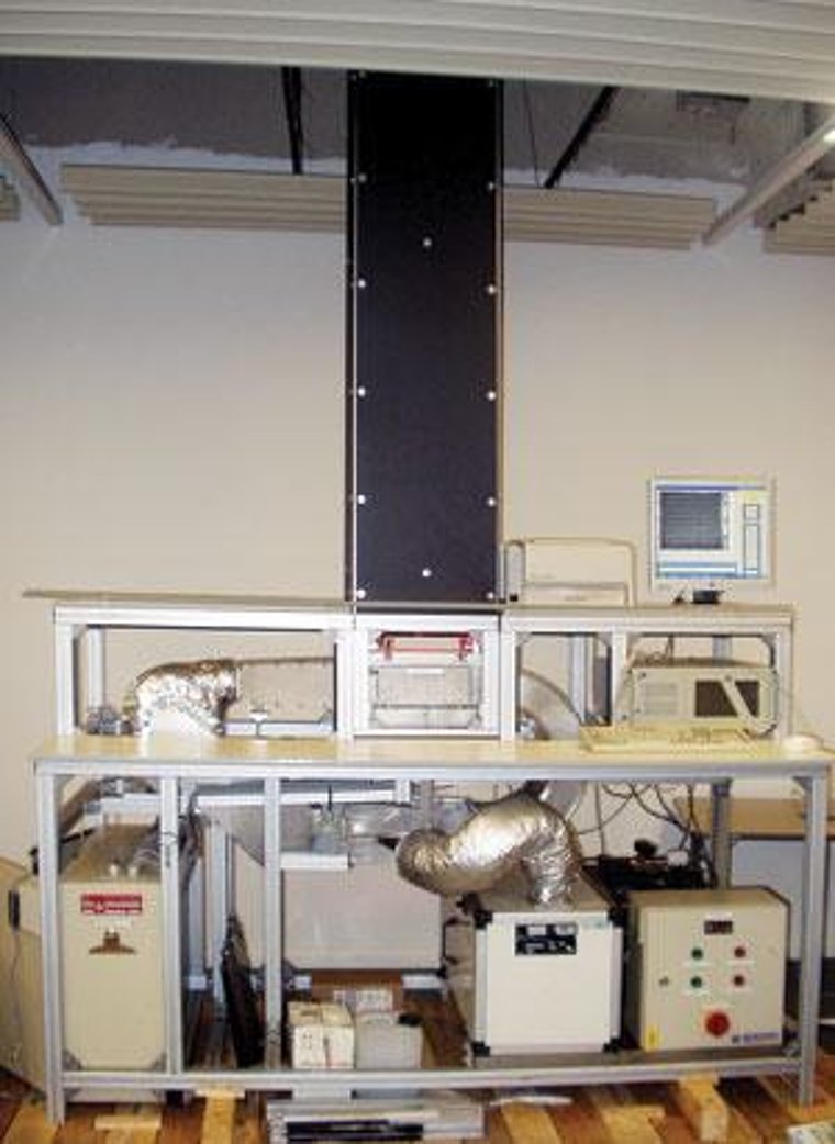
To achieve sufficient throughput with the one-hour testing cycle, Sensata temporarily groups 32 strips into an array of 1024 bimetal disks (Fig. 2). The array is then loaded into a proprietary oven developed by TCPM to hold and heat the array.
The oven is a metal enclosure with glass plates for a roof, as well as two sides and open vets on the other two sides to allow forced heated air to pass through the enclosure. High-frequency, high-output fluorescent lights shine through the glass walls of the enclosure to illuminate the array from all sides and reduce shadows. Initially, TCPM used red LEDs with a red filter placed over the camera to improve contrast, but the press plates that form the roof of the oven did not let sufficient light through to make a good image. A metal nest is attached to the floor of the oven to hold the bimetal disk array in place.
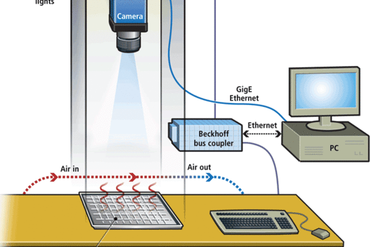
Above the oven is the camera enclosure. A 1600 × 1200-pixel Prosilica CCD camera with Gigabit Ethernet output is mounted at the top of the enclosure (Fig. 3). TCPM used standard optics and a longer stand-off distance to reduce optical distortion of the bimetal disks while keeping costs down.
"You have to have the camera relatively high in the chamber to get an accurate field of view," notes TCPM's Slatius. "If it's too close, you get distorted images of the disks on the edges. We just use a standard 35-mm C-mount lens. We went with a Prosilica GigE camera because we wanted to do all the processing at the PC, so we needed high bandwidth, and not all PCs have FireWire ports."

Getting hotter
After the array is loaded into the oven, the operator initiates the system via an operator interface and supervisory program written in Microsoft Visual Basic (VB) that runs on a generic desktop PC with Windows XP. The VB shell program sends a signal via Ethernet I/O to a Beckhoff EtherCAT BK1120 expandable bus coupler. The BK1120 acts as a switch to control all nonimaging peripherals, including the heater located below the oven, a fan to move the heated air through the test oven, the two HF/HO fluorescent lights, and six Pt100 platinum resistance thermometers (Fig.4).
"The thermometers provide temperature readings from different parts of the oven for greater accuracy and also feed a separate safety circuit connected to the EtherCAT bus that ensures the temperature does not exceed the maximum of 200°C," explains Slatius.
"The temperature values are also sent through the Beckhoff bus coupler to the PC for recording the temperature values when a bimetal disk snaps." As the temperature is gradually increased inside the oven, the Prosilica camera captures images at the rate of 5 frames/s. "The camera operates at rates up to 15 frames/s but only uses 5 frames/s and could probably get by with 2 frames/s," explains Slatius.
Each image is fed across Cat 5 cable to the PC. HALCON algorithms take over, first filtering the image, then locating bimetal disks. "First, we filter the image to get rid of noise and reflections from the safety windows. Sometimes, we also get reflections from the base-metal strip; knowing the distance between disks helps us to filter out these reflections and focus on the disk," continues Slatius.
"After filtering, we use a blob algorithm to determine the location of each bimetal disk and track the movement for each disk from frame to frame. When the percentage change exceeds a certain value, we say the snap has occurred. The system then records the temperature value from the closest PRT sensor, plus the numbered location of the disk in the array under test. The system records these values in a text file that can be imported into an Excel spreadsheet for final review by production staff.
"We also look at the average snap temperature per batch and use that as a way to track changes in the bimetal disk stamping and welding process. By tracking the sigma value, the customer can track tool wear and quality level of the production line," says Slatius.
According to Slatius, future enhancements to the system will include the use of a thermal model of the oven in determining the switching temperature to get a more accurate result, which should lead to a shorter cycle time, faster feedback, and improved production yield.
Author: Winn Hardin
Article kindly provided by Vision Systems Design. TCPM is an MVTec Certified Integration Partner All product names, trademarks and images of the products/trademarks are copyright by their holders. All rights reserved.
