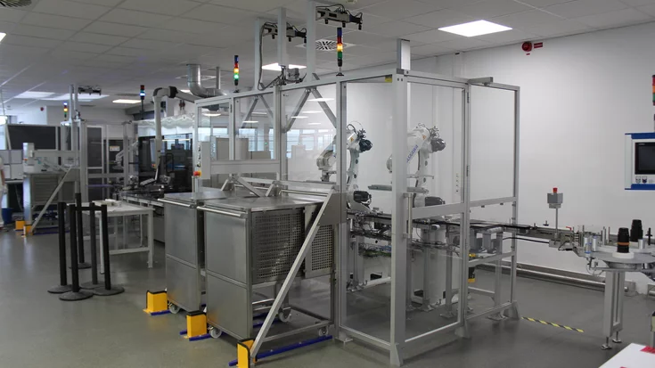
Vision system checks pharmaceutical products - Machine Vision Technology

Medical Supplies & Pharmaceutical | Inspection | Matching | Measuring | Morphology
Figure 1
Fig. 1: Tablets or capsules are placed into a hopper at the rear of the machine. From the hopper, they are fed onto a vibratory feed system that separates the products from one another. When the tablets or capsules leave the vibratory feed system, they pass through high speed infrared optical sensors that count the products in free fall after which they are guided into separate containers through chutes and filling nozzles.

A vision system has been retrofitted to a counting and bottling machine to check for broken or partially formed tablets and capsules.

In the pharmaceutical industry, it is critically important to count tablets and gel capsules prior to filling them into containers. To meet those demands, Pharma Packaging Systems (Worcestershire, England; www.pharmaps.com) has developed a range of electronic counting and packaging systems that can be deployed either as stand-alone units or as part of an integrated packaging line. To enhance the capability of their existing product range, the company recently joined forces with Machine Vision Technology (Warwickshire, England; www.machine-vision-technology.co.uk) to create a vision-based inspection system that can detect partially formed and broken tablets and capsules and determine whether any cross contamination had occurred. Counting and packaging In a typical counting and packaging machine, tablets or capsules are placed into a hopper at the rear of the machine, either manually or automatically. From the hopper they are fed onto a vibratory feed system divided into three sets of three stainless steel cascading feed trays, each having six tracks. The grooved vibrating sections of the feed trays separate the products from one another as they move along tracks. When the tablets or capsules leave the end of the last of the three feed trays, they pass through high speed infrared optical sensors that count the products in free fall before they are guided into individual bottles through chutes and filling nozzles (Figure 1). To determine whether a container has been filled correctly, the data from the sensors is fed to an embedded PC which counts the number of tablets that have been deposited into each bottle.

Once one of the bottles in the machine has been filled, the PC then closes a flap and eventually halts the vibratory feed system associated with it until the other bottles have been filled. The bottles are then indexed through the system and either accepted or rejected, depending on whether they have been filled correctly. Vision enhancement To enable the machine to check for broken or partially formed tablets, Machine Vision Technology mounted three Scout 1300 32gc 1250 x 1000 pixel cameras from Basler (Ahrensburg, Germany; www.baslerweb.com/en fitted with 12mm lenses from Computar (Cary, North Carolina, USA; www.computar.com ) above each one of the final three vibrating feed trays of the counting and bottling machine. To illuminate the trays, a dark field lighting system was developed that comprises a bank of four LED line lights which project light at an angle down onto the trays. The dark field lighting technique ensures that the light incident on the mirrored surface of the stainless steel feed trays is reflected away from-rather than directly at-the cameras, enabling images of the matt surface of the tablets or capsules to be imaged effectively. Images of the tablets or capsules on the trays are transferred to a dedicated PC over GigE interfaces where they are processed using HALCON image processing software from MVTec (Munich, Germany). The primary purpose of the inspection is to identify small particles or half tablets that might be present and to determine whether the tablets are of the correct color. To do so, the HALCON software analyzes the images of the tablets to determine the length, width, area, completeness, and verifies their color. The PC-based vision inspection system is interfaced to the embedded PC performing the counting function to which it communicates in real time. If a tablet is identified as defective by the vision system, it will still be bottled by the machine. However, the PC running the vision system software will then flag the tablet as defective and send a fail signal to the embedded PC performing the counting function. The embedded PC then decides which container contains the incorrect tablet depending upon when the fail signal was received from the vision system. Having done so, the container will then be rejected from the line after it leaves the bottling machine. Sophisticated software The LED lighting used in the system is mounted in an enclosure above the trays together with the three cameras. Because the lighting is positioned around all four sides of the enclosure illuminating each of the three trays at an angle, illumination consistency varies across the three cascading feed trays beneath the system. Hence it was important to ensure that the images of the tablets or capsules could be segmented from the background image of the trays no matter which tray they were on. To do so, the vision system employs an image thresholding algorithm that segments the images based on the intensity values of the pixels in the image.

Rather than choose a fixed threshold value, however, the system uses a local adaptive thresholding technique to separate desirable foreground image objects from the background. Individually tuning the threshold values for each lane of feed trays provides a more robust solution to accommodate changes in illumination across the trays. Because many tablets or capsules may be touching as they move down the trays, a means was needed to digitally separate them prior to making measurements on their size and color. To do so, the vision software makes use of erosion and dilation operators found in the HALCON toolset. In use, the erosion operation removes a given number of pixels from around the outer perimeter of the objects identified in the image. If the product has been eroded correctly, touching products are then separated into separate objects. What is more, smaller objects in the image, such as dust, the thin reflections from the grooves in the tray or the small regions due to the reflections of the product in the sides of the grooves in the trays disappear.

Figure 2
Fig. 2: While in supervisor mode, an operator names a new product to be inspected, and places several products over each track of each tray. The camera aperture or exposure time of each of the cameras can then be modified to ensure that the tablets can be appropriately imaged by the system.

Next, the images are dilated to their original size by adding pixels around their edges. The vision system can then perform measurements to determine their width, length and area. In some instances, capsules may have a pharmaceutical manufacturer's logo printed onto them. If the printed logo is on the very perimeter of the tablet when an image of the tablet is captured by the camera, the capsule may appear to have an occlusion on one side. Hence measuring the width of the tablet would be compromised. To overcome this issue, a HALCON convex hull operation is performed on the images of a tablet to eliminate the impact of concaved areas in the image, enabling an accurate measurement of its width to be made. Setup and training Prior to use, the vision system fitted to the counting and bottling machine must be taught the characteristics of a new product. To do so, an operator allocates a name to the product on an HMI and places the new tablets or capsules to be inspected over each track of the trays. The camera aperture or exposure time of each of the cameras can then be modified to ensure that the tablets can be appropriately imaged by the system (Figure 2). Once an image has been captured of products on a tray, threshold levels can be set on the images to highlight all of the tablets in the image, while eliminating the background of the tray and any reflections of the product from the sides of the grooves in the tray. Having done so, an operator can highlight each of the tablets on the tray by assigning a single color to all of them (Figure 3).

The operator then sets the levels of erosion and dilation necessary to separate touching products. If the product has been eroded correctly, the operator will immediately visualize this on screen, as the touching products will appear as separate objects. The image can then be dilated to make all the tablets appear their normal size, so that the vision system can calculate their length, width and area (Figure 4). Once the appropriate levels of erosion and dilation have been set, the system can be trained to recognize the color of the tablet. Here, the operator highlights the tablet which best represents the true tablet color. The system then takes the red, green and blue components of the pixel plus the pixels immediately surrounding it, averages them and obtains a value for red, green and blue. This then becomes the value for the color of the new tablet. Tablet tracking As the tablets or capsules move down the trays, they are vibrating, touching and often bouncing. This presented a challenge for the vision system, which was required to identify the tablets or capsules despite the fact that they could be presented to the cameras in the system in various orientations. Compounding the inspection challenge was the fact that the vibratory feeders start and stop several times a minute and can feed the tablets into the containers at varying rates. To resolve this, Machine Vision Technology spent over one year developing tablet tracking software. When the system is running, the cameras capture ten or more images of each tablet in each of the trays at a rate of 20fps as they pass from top to bottom through the cameras' fields of view. Once the vision system has found a tablet or capsule in each image, it then predicts where it will be in the next image. Then, it matches its new position and orientation in the new image with its position and orientation in the previous image to identify it as the same tablet. Once the inspection returns a 'good' result for a tablet it is 'locked-in' as good, even if it then bounces onto an edge and so appears to be 'bad' in subsequent inspections.

As the tablet leaves the tray and gets counted into a bottle, the vision system outputs the tablet inspection result. The tablet must be deemed 'good' in at least one image, otherwise it is 'bad' and the bottle it goes into automatically gets segregated to a reject area. As the system inspects the tablets or capsules, an operator can immediately visualize the total number of tablets inspected by the machine on the HMI, as well as the total number that have passed or failed the inspection (Figure 5). Looking ahead Although the machines described above are the standard Pharma Packaging Systems' machines retrofitted with machine vision, the latest machine jointly developed by Pharma Packaging Systems and Machine Vision Technology also ensures that only good product is discharged for further processing. In the new design, products are transferred from a vibratory system onto a flat belt where they are inspected by the vision system for width, length, area and color. Should the vision system detect any products that do not fall within specification, it triggers a series of electromechanical reject chutes positioned at the end of the belt into which the faulty products are dropped. The new system-which was recently installed at a large UK tablet manufacturer-can inspect up to 10,000 tablets per minute. The products used in the design of the system were supplied and supported by Multipix Imaging (Petersfield, England; www.multipix.com).

Author: Brian Castelino Machine Vision Technology Ltd. (MVT) is a MVTec Certified Integration Partner.

Article kindly provided by Vision Systems Design. All product names, trademarks and images of the products/trademarks are copyright by their holders.
All rights reserved.